Infiniti M35/M45 Y50. Manual - part 172
SYSTEM DESCRIPTION
AV-65
[WITHOUT MOBILE ENTERTAINMENT SYSTEM]
C
D
E
F
G
H
I
J
L
M
A
B
AV
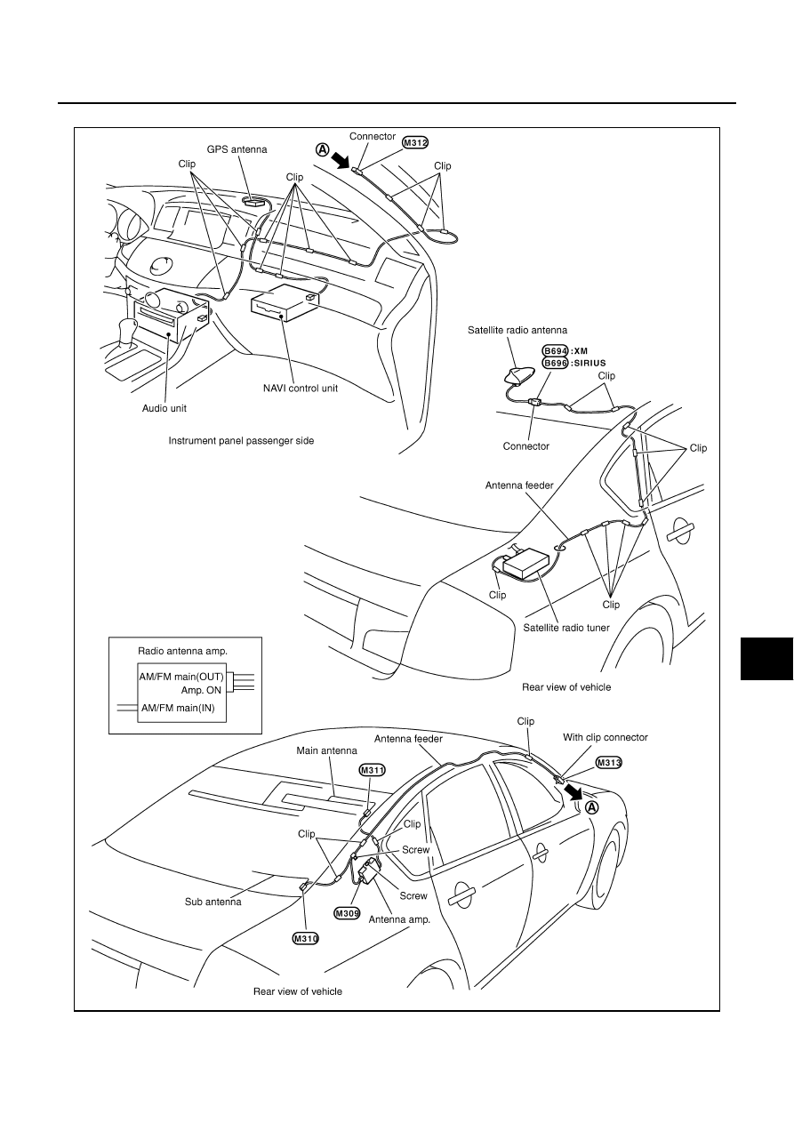
Location of Antenna
NKS0048K
SKIB8873E
|
|
|
SYSTEM DESCRIPTION AV-65 [WITHOUT MOBILE ENTERTAINMENT SYSTEM] C D E F G H I J L M A B AV Location of Antenna NKS0048K SKIB8873E |