Infiniti M35/M45 Y50. Manual - part 144
SUNLOAD SENSOR
ATC-127
C
D
E
F
G
H
I
K
L
M
A
B
ATC
SUNLOAD SENSOR
PFP:27721
Removal and Installation
NJS000H8
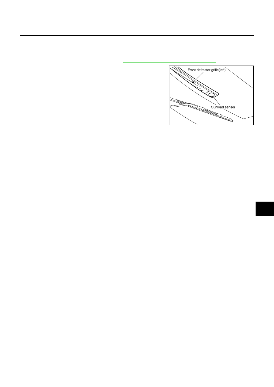
REMOVAL
1.
Remove front defroster grille (left). Refer to
IP-10, "INSTRUMENT PANEL ASSEMBLY"
.
2.
Disconnect sunload sensor connector, and then remove sunload
sensor.
INSTALLATION
Installation is basically the reverse order of removal.
RJIA4110E