Infiniti M35/M45 Y50. Manual - part 133
TROUBLE DIAGNOSIS
ATC-83
C
D
E
F
G
H
I
K
L
M
A
B
ATC
SYSTEM DESCRIPTION
Component Parts
Air mix door control system components are:
●
Unified meter and A/C amp.
●
Air mix door motor (LCU)
●
A/C LAN system (PBR built-in mode door motor, upper ventilator door motor, air mix door motor and
intake door motor)
●
In-vehicle sensor
●
Ambient sensor
●
Sunload sensor
●
Intake sensor
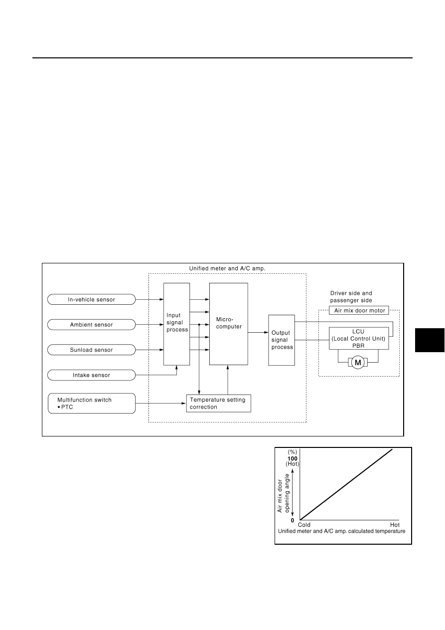
System Operation
The unified meter and A/C amp. receives data from each of the sensors. The unified meter and A/C amp.
sends air mix door, mode door, upper ventilator door and intake door opening angle data to the air mix door
motor LCUs, mode door motor LCUs, upper ventilator door motor LCU and intake door motor LCU.
The air mix door motors, mode door motors, upper ventilator door motor and intake door motor read their
respective signals according to the address signal. Opening angle indication signals received from the unified
meter and A/C amp. and each of the motor position sensors are compared by the LCUs in each door motor
with the existing decision and opening angles. Subsequently, HOT/COLD, DEF/VENT, OPEN/SHUT and FRE/
REC operation is selected. The new selection data are returned to the unified meter and A/C amp.
Air Mix Door Control Specification
RJIA4217E
RJIA1782E