Infiniti M35/M45 Y50. Manual - part 120
AIR CONDITIONER CONTROL
ATC-31
C
D
E
F
G
H
I
K
L
M
A
B
ATC
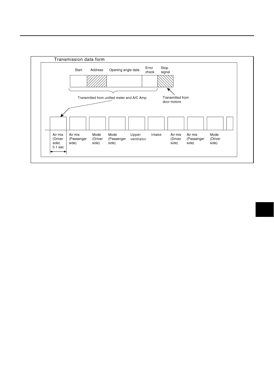
Stop signal:
At the end of each transmission, a stop operation, in-operation, or internal malfunction message is delivered to
the unified meter and A/C amp. This completes one data transmission and control cycle.
AIR MIX DOOR CONTROL (AUTOMATIC TEMPERATURE CONTROL)
The air mix doors are automatically controlled so that in-vehicle temperature is maintained at a predetermined
value by the temperature setting, ambient temperature, in-vehicle temperature and amount of sunload.
FAN SPEED CONTROL
Blower speed is automatically controlled by the temperature setting, ambient temperature, in-vehicle tempera-
ture, intake temperature, amount of sunload and air mix door position.
With pressing AUTO switch, the blower motor starts to gradually increase air flow volume.
When engine coolant temperature is low, the blower motor operation is delayed to prevent cool air from flow-
ing.
INTAKE DOOR CONTROL
The intake doors are automatically controlled by the temperature setting, ambient temperature, in-vehicle tem-
perature, intake temperature, amount of sunload and ON/OFF operation of the compressor.
MODE DOOR CONTROL
The mode doors are automatically controlled by the temperature setting, ambient temperature, in-vehicle tem-
perature, intake temperature and amount of sunload.
UPPER VENTILATOR DOOR CONTROL
The upper ventilator door is automatically controlled by the mode setting, and amount of sunload.
RJIA4019E