Content .. 1152 1153 1154 1155 ..
Infiniti M35/M45 Y50. Manual - part 1154
FRONT WIPER AND WASHER SYSTEM
WW-21
C
D
E
F
G
H
I
J
L
M
A
B
WW
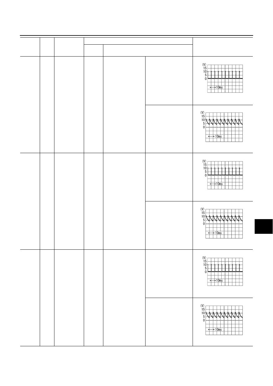
33
GR
Combination
switch output 4
ON
Lighting, turn, wiper
OFF
(Wiper dial position 4)
Any of several con-
ditions below
●
Wiper dial position 1
●
Wiper dial position 5
●
Wiper dial position 6
Approx. 1.2 V
OFF
(Wiper dial position 4)
Approx. 7.0 - 7.5 V
34
L
Combination
switch output 3
ON
Lighting, turn, wiper
OFF
Any of several con-
ditions below
●
Wiper dial position 1
●
Wiper dial position 2
●
Wiper dial position 3
Approx. 1.2 V
OFF
(Wiper dial position 4)
Approx. 7.0 - 7.5 V
35
SB
Combination
switch output 2
ON
Lighting, turn, wiper
OFF
(Wiper dial position 4)
Any of several con-
ditions below
●
Front wiper switch INT
●
Front wiper switch HI
Approx. 1.2 V
OFF
Approx. 7.0 - 7.5 V
Terminal
No.
Wire
color
Signal name
Measuring condition
Reference value
Ignition
switch
Operation or condition
PKIB4958J
PKIB4960J
PKIB4958J
PKIB4960J
PKIB4958J
PKIB4960J