Infiniti M35/M45 Y50. Manual - part 1122


  Index      Infiniti     Infiniti M35/M45 Y50 - service repair manual 2007 year


Search            copyright infringement  


Content   ..  1120  1121  1122  1123   ..


Infiniti M35/M45 Y50. Manual - part 1122


TROUBLE DIAGNOSIS

STC-45

[RAS]

C

D

E

F

H

I

J

K

L

M

A

B

STC

Inspection 10: Stop Lamp Switch Harness

NGS000EZ

1. 

CHECK STOP LAMP SWITCH SIGNAL

With CONSULT-II

Select “STOP LAMP SW” on DATA MONITOR, and then check the stop lamp switch.
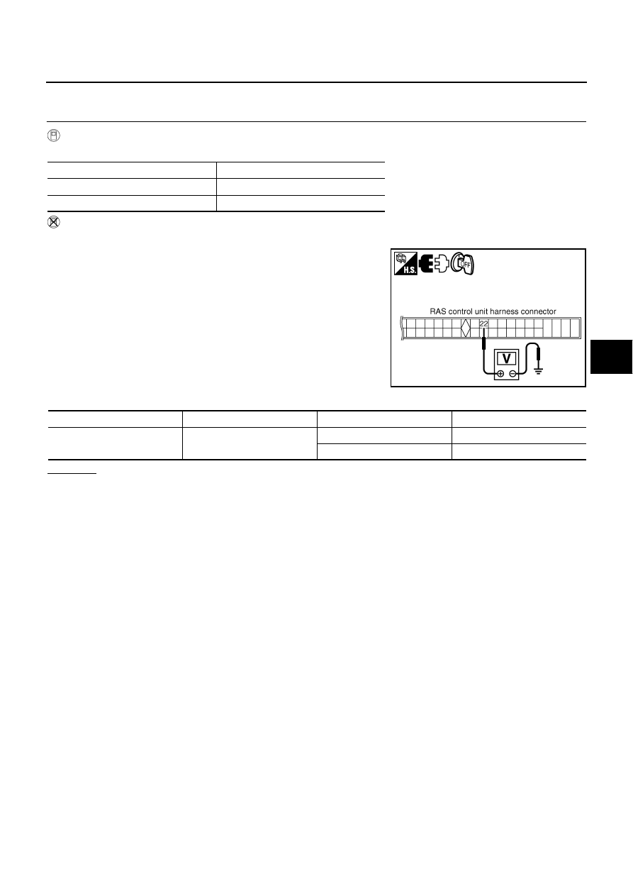
Without CONSULT-II

1.

Turn ignition switch OFF, disconnect RAS control unit harness connector B476.

2.

Operate brake pedal, and then check voltage between RAS con-
trol unit harness connector B476 and ground.

OK or NG

OK

>> Stop lamp switch harness is normal.

NG

>> Stop lamp switch harness malfunction. Repair circuit.

Measuring condition

Data monitor

Brake pedal depressed

ON

Brake pedal released

OFF

SGIA1277E

RAS C/U

Ground

Measuring condition

Voltage

Terminal 22

Brake pedal depressed

Battery voltage (approx. 12 V)

Brake pedal released

Approx. 0 V

STC-46

[RAS]

TROUBLE DIAGNOSIS

Inspection 11: RAS Warning Lamp Harness

NGS000F0

1. 

CHECK RAS WARNING LAMP SIGNAL

Turn ignition switch ON, and then check voltage between RAS con-
trol unit harness connector B476 and ground.

OK or NG

OK

>> Perform self-diagnosis. Refer to 

STC-28, "SELF-DIAG

RESULT MODE"

 .

NG

>> GO TO 2.

2. 

CHECK RAS WARNING LAMP HARNESS

1.

Turn ignition switch OFF, disconnect RAS control unit harness connector B476 and combination meter
harness connector M52.

2.

Check continuity between RAS control unit harness connector
B476 and combination meter harness connector M52.

3.

Check continuity between RAS control unit harness connector
B476 and ground.

OK or NG

OK

>> GO TO combination meter power supply circuit.

NG

>> Harness between RAS control unit and combination

meter open or shorted. Repair or replace harness.

RAS control unit

Ground

Voltage

Terminal 26

Warning lamp OFF

: Approx. 2.8 V or more

Warning lamp ON

: Approx. 1.4 V or less

SGIA1278E

Terminal 26 

 19

: Continuity should exist.

SGIA1279E

Terminal 26 

 Ground

: Continuity should not exist.

SGIA1280E

TROUBLE DIAGNOSIS

STC-47

[RAS]

C

D

E

F

H

I

J

K

L

M

A

B

STC

Diagnosis Chart by Symptom 1

NGS000F1

1. 

CHECK SELF-DIAGNOSTIC RESULTS

Perform RAS self-diagnosis.

With CONSULT-II: 

STC-28, "SELF-DIAG RESULT MODE"

Without CONSULT-II: 

STC-31, "Diagnosis Procedure with Self-Diagnosis Function (Without CONSULT-

II)"

Are malfunctioning items displayed in self-diagnosis results?

YES

>> Repair or replace any malfunctioning items.

NO

>> GO TO 2.

2. 

CHECK RAS STATIC/DYNAMIC CHARACTERISTICS

Check RAS static/dynamic characteristics. Refer to 

STC-49, "Check RAS Static/Dynamic Characteristics"

 .

Is the malfunction corrected?

YES

>> INSPECTION END

NO

>> Perform the following check, and then check the symptom again.

Adjust neutral position of steering angle sensor. Refer to 

BRC-6, "Adjustment of Steering Angle

Sensor Neutral Position"

 .

Steering angle sensor mounting condition. Refer to 

BRC-60, "Removal and Installation"

 .

Diagnosis Chart by Symptom 2

NGS000F2

The steering force does not change smoothly according to the vehicle speed (Heavy steering force with the
vehicle stopped/Light handle operation during high-speed driving)

1. 

CHECK (1): POWER STEERING SOLENOID VALVE SIGNAL

1.

Start engine.

2.

Change the vehicle speed from 0 to 100 km/h (0 to 62 MPH)
slowly, and then check voltage RAS control unit harness con-
nector B476.

OK or NG

OK

>> GO TO 2.

NG

>> GO TO 7.

2. 

CHECK (2): POWER STEERING SOLENOID VALVE SIGNAL

1.

Activate fail-safe function by running engine speed at 1,500 rpm or higher for 10 seconds with the vehicle
stopped.

2.

Change the engine speed to the idling speed, approx. 1,600
rpm, and approximately 3,000 rpm slowly, and then check volt-
age RAS control unit harness connector B476.

OK or NG

OK

>> GO TO 3.

NG

>> GO TO 7.

Terminal 36 – 34

: The voltage has changed from 
approximately 4.4 - 6.6 V to approxi-
mately 2.4 - 3.6 V.

SGIA1281E

Terminal 36 – 34

: The voltage is changed from 
approximately 5.5 V to approximately 
2.1 V step-by-step.

SGIA1281E

STC-48

[RAS]

TROUBLE DIAGNOSIS

3. 

CHECK POWER STEERING SOLENOID VALVE CONNECTOR

Turn ignition switch OFF, disconnect power steering solenoid valve harness connector, and check terminal for
deformation, disconnection, looseness, etc.

OK or NG

OK

>> GO TO 4.

NG

>> Harness or connector open or shorted. Repair or replace any inoperative parts.

4. 

CHECK POWER STEERING SOLENOID VALVE POWER SUPPLY CIRCUIT

Check continuity between RAS control unit harness connector B476
(A) and power steering solenoid valve harness connector F25
(VQ35DE), E211 (VK45DE) (B).

OK or NG

OK

>> GO TO 5.

NG

>> Open or short in harness. Repair or replace any inoper-

ative parts.

5. 

CHECK POWER STEERING SOLENOID VALVE GROUND CIRCUIT

Check continuity between power steering solenoid valve harness
connector F25 (VQ35DE), E211 (VK45DE) and ground.

OK or NG

OK

>> GO TO 6.

NG

>> Open or short in harness. Repair or replace any inoper-

ative parts.

6. 

CHECK POWER STEERING SOLENOID VALVE

Apply voltage power steering solenoid valve connector F25
(VQ35DE), E211 (VK45DE) and then make sure that the operating
sound (clicking sound) is heard.

OK or NG

OK

>> Perform steering wheel turning force inspection. Refer

to 

PS-10, "CHECKING STEERING WHEEL TURNING

FORCE"

 .

NG

>> Power steering solenoid valve is inoperating. Replace it.

7. 

CHECK SELF-DIAGNOSIS RESULTS

Perform RAS self-diagnosis.

With CONSULT-II: 

STC-28, "SELF-DIAG RESULT MODE"

Without CONSULT-II: 

STC-31, "Diagnosis Procedure with Self-Diagnosis Function (Without CONSULT-

II)"

Are malfunctioning items displayed in self-diagnosis results?

YES

>> Repair or replace any malfunctioning items.

NO

>> RAS control unit malfunction. Replace it.

RAS C/U

Power steering solenoid valve

Continuity

Terminal 36

Terminal 1

Yes

SGIA1652E

Terminal 2 – Ground

: Continuity should exist.

SGIA1283E

Terminal 1 (+) - 2 (-)

: Operating sound is heard.

SGIA1284E


Content   ..  1120  1121  1122  1123   ..