Content .. 1096 1097 1098 1099 ..
Infiniti M35/M45 Y50. Manual - part 1098
SUPPLEMENTAL RESTRAINT SYSTEM (SRS)
SRS-7
C
D
E
F
G
I
J
K
L
M
A
B
SRS
Occupant Classification System (OCS)
NHS0008W
The occupant classification system identifies different size occupants, out of position occupants, and detects if
child seat is present in the front passenger seat. The occupant classification system receives inputs from the
occupant classification sensor (located inside the passenger seat cushion assembly) and belt tension sensor
(part of the passenger front seat belt assembly and located at the belt anchor location). Depending on classifi-
cation of passenger, the occupant classification system sends a signal to the diagnosis sensor unit. The diag-
nosis sensor unit uses this signal to determine full, partial, or non deployment of passenger front air bag in the
event of a collision. Depending on the signal received, the diagnosis sensor unit can disable the passenger
front air bag completely.
NOTE:
In case of customer concern, CONSULT-ll can be used to confirm the passenger air bag status (readiness).
Passenger Air Bag Status Condition
NHS0008X
NOTE:
Passenger does not meet Ocuupant Classification System specifications for passenger air bag activation.
Component Parts of Occupant Classification System
NHS0008Y
Front Passenger Seat
(Condition)
PASS AIR BAG OFF Indicator
(Status)
Passenger Air Bag Status
(Readiness)
CONSULT-ll Display
Seat occupied
OFF
Active (enabled)
ON
seat occupiedNOTE
ON
Deactivated (disabled)
OFF
Seat empty
OFF
Deactivated (disabled)
OFF
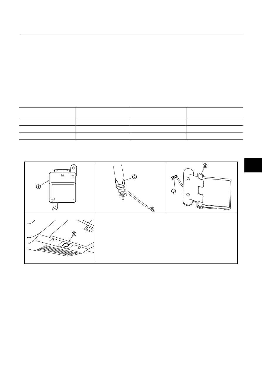
PHIA1177E
1.
Occupant classification system con-
trol unit
2.
Belt tension sensor
3.
Seat pressure sensor
4.
Bladder
5.
Front passenger air bag OFF indica-
tor (Cutoff telltaile)