Infiniti M35/M45 Y50. Manual - part 106


  Index      Infiniti     Infiniti M35/M45 Y50 - service repair manual 2007 year


Search            copyright infringement  


Content   ..  104  105  106  107   ..


Infiniti M35/M45 Y50. Manual - part 106


ASSEMBLY

AT-347

D

E

F

G

H

I

J

K

L

M

A

B

AT

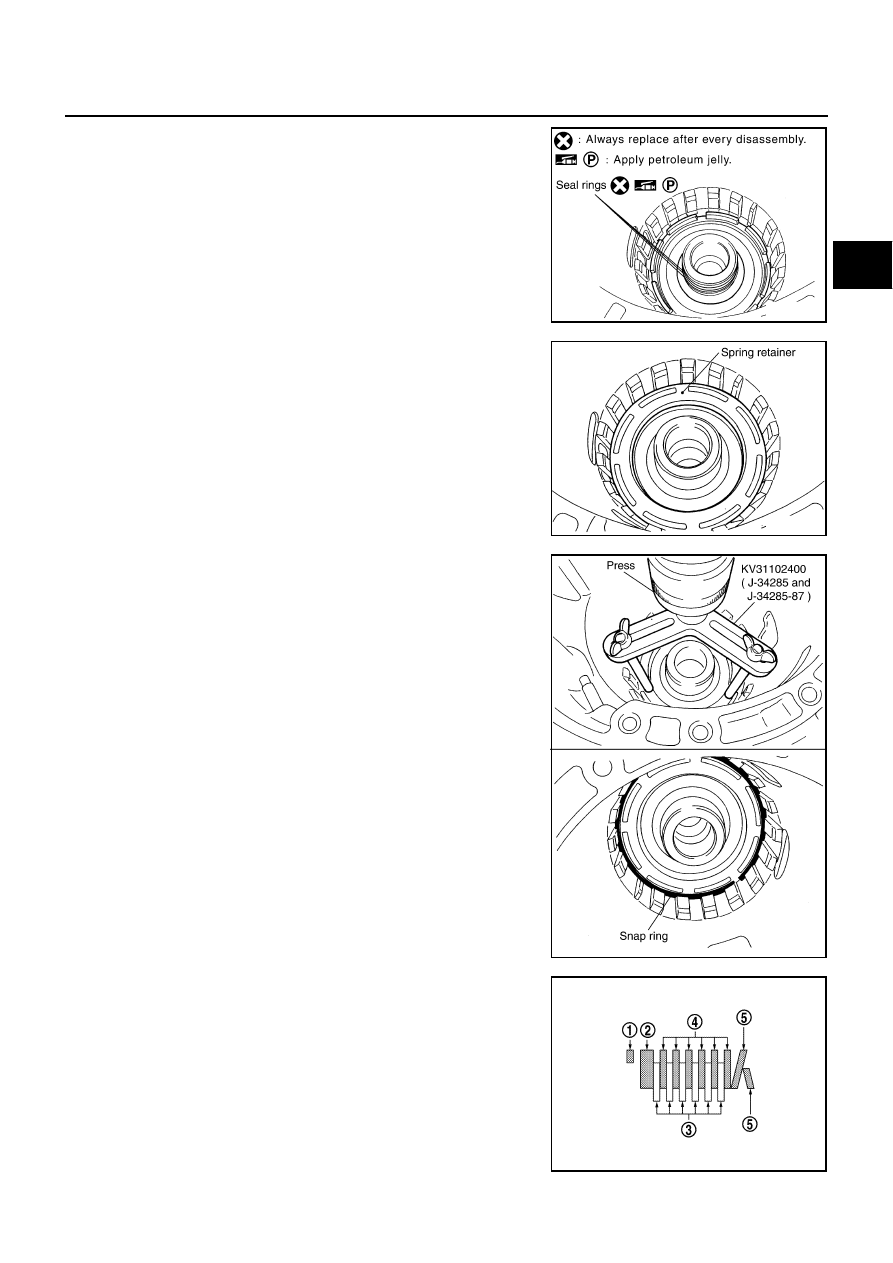
15. Install seal rings to drum support.

CAUTION:

Do not reuse seal rings.

Apply petroleum jelly to seal rings.

16. Install spring retainer and return spring in transmission case.

17. Set the SST on spring retainer and install snap ring (fixing spring

retainer) in transmission case while compressing return spring.

CAUTION:

Securely assemble them using a flat-bladed screwdriver so
that snap ring tension is slightly weak.

18. Install reverse brake drive plates, driven plates and dish plates

in transmission case.

CAUTION:

Take care with order of plates.

Snap ring (1)

Retaining plate (2)

Drive plate (3)

Driven plate (4)

Dish plate (5)

Drive plate/Driven plate: 6/6

SCIA3333E

SCIA2324E

SCIA5877E

SCIA6949E

AT-348

ASSEMBLY

19. Assemble N-spring.

20. Install reverse brake retaining plate in transmission case.

21. Install snap ring in transmission case.

22. Measure clearance between retaining plate and snap ring. If not

within specified clearance, select proper retaining plate.

23. Install needle bearing to transmission case.

CAUTION:

Take care with the direction of needle bearing. Refer to

AT-298, "Locations of Adjusting Shims, Needle Bearings,
Thrust Washers and Snap Rings"

 .

Apply petroleum jelly to needle bearing.

SCIA5249E

SCIA2439E

Specified clearance A

Standard: 0.7 - 1.1 mm (0.028 - 0.043 in)

Retaining plate

Refer to 

AT-372, "Reverse Brake"

 .

SCIA3129E

SCIA5031E

ASSEMBLY

AT-349

D

E

F

G

H

I

J

K

L

M

A

B

AT

24. Install revolution sensor to transmission case. Tighten revolution

sensor bolt to the specified torque. Refer to 

AT-281, "Compo-

nents"

 .

CAUTION:

Do not subject it to impact by dropping or hitting it.

Do not disassemble.

Do not allow metal filings, etc., to get on the sensor's
front edge magnetic area.

Do not place in an area affected by magnetism.

25. Assemble one of the following parts.

Rear extension assembly (VQ35DE models for 2WD)

Adapter case assembly (AWD models)

Output shaft & companion flange complement (VK45DE models for 2WD)

a.

VQ35DE models

i.

As shown in the figure, use the drift to drive rear oil seal into the
rear extension (2WD models) or adapter case (AWD models)
until it is flush.

CAUTION:

Apply ATF to rear oil seal.

Do not reuse rear oil seal.

ii.

Install return spring (1) to parking pawl (2).

SCIA2320E

SCIA5477E

SCIA6180J

AT-350

ASSEMBLY

iii.

Install parking pawl (with return spring) and pawl shaft to rear
extension (2WD models) or adapter case (AWD models).

iv.

Install parking actuator support from rear extension (2WD mod-
els) or adapter case (AWD models).

v.

Install needle bearing (1) to rear extension (2WD models) or
adapter case (AWD models).

CAUTION:

Take care with the direction of needle bearing. Refer to

AT-298, "Locations of Adjusting Shims, Needle Bearings,
Thrust Washers and Snap Rings"

 .

Apply petroleum jelly to needle bearing.

Refer to GI section to make sure icons (symbol marks) in the fig-
ure. Refer to 

GI-11, "Components"

 .

b.

VK45DE models

i.

Install return spring (1) to parking pawl (2).

SCIA3424E

SCIA3423E

SCIA6179J

SCIA6180J


Content   ..  104  105  106  107   ..