Content .. 1019 1020 1021 1022 ..
Infiniti M35/M45 Y50. Manual - part 1021
FRONT OIL SEAL
RFD-11
C
E
F
G
H
I
J
K
L
M
A
B
RFD
6.
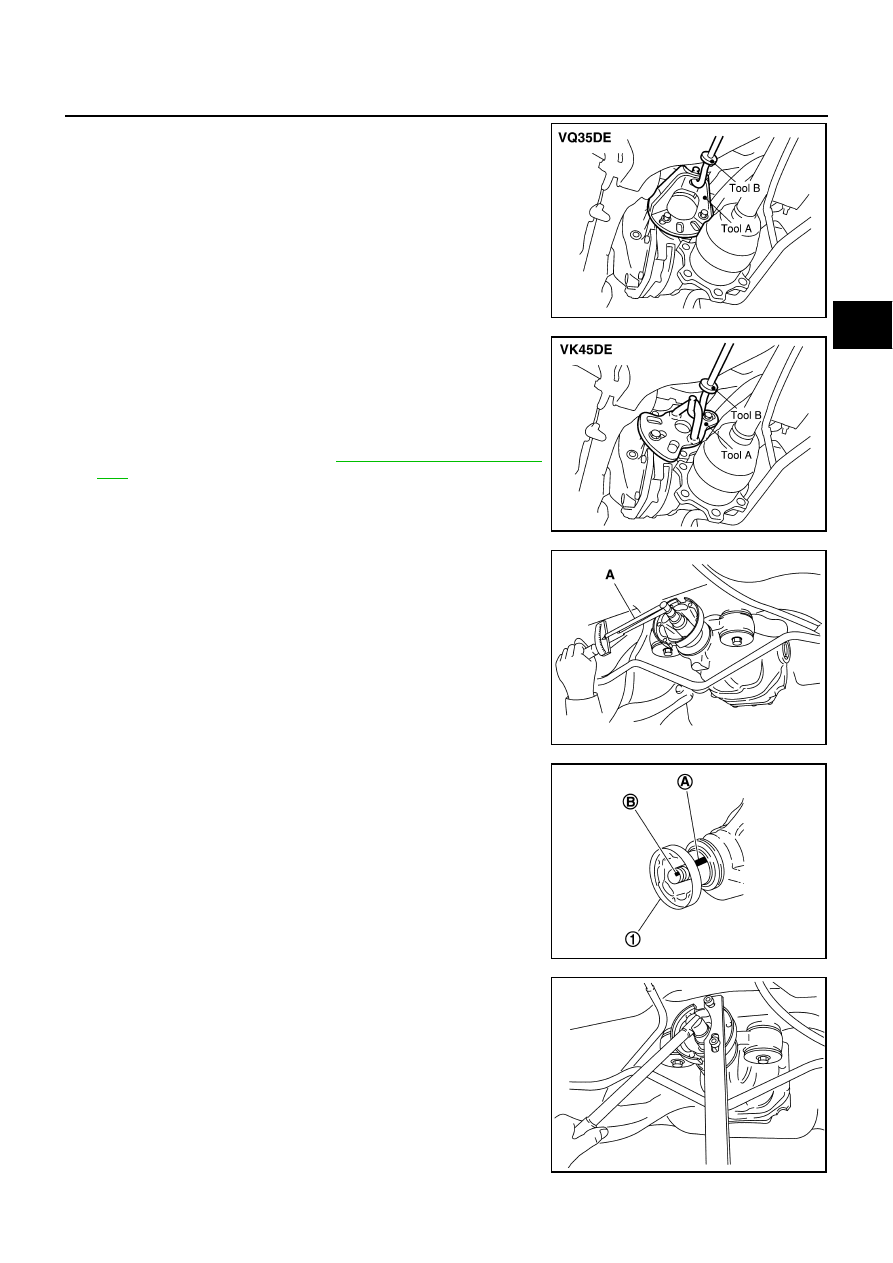
Install attachment to side flange, and then pull out the side
flange with the sliding hammer.
●
For VQ35DE models
NOTE:
Circular clip installation position: Final drive side
●
For VK45DE models
NOTE:
Circular clip installation position: Final drive side
7.
Remove propeller shaft. Refer to
8.
Measure the total preload with the preload gauge.
NOTE:
Record the preload measurement.
9.
Put matching mark (B) on the end of the drive pinion. The
matching mark (B) should be in line with the matching mark (A)
on companion flange (1).
CAUTION:
For matching mark, use paint. Do not damage companion
flange and drive pinion.
NOTE:
The matching mark (A) on the final drive companion flange (1)
indicates the maximum vertical runout position.
10. Remove drive pinion lock nut using the flange wrench.
Tool number
A: KV40104100 (
—
)
B: ST36230000 (J-25840-A)
SDIA1582E
Tool number
A: KV40101000 (
—
)
B: ST36230000 (J-25840-A)
SDIA1583E
Tool number
A: ST3127S000 (J-25765-A)
PDIA0977E
PDIA0750J
PDIA0978E