Infiniti M35/M45 Y50. Manual - part 89


  Index      Infiniti     Infiniti M35/M45 Y50 - service repair manual 2007 year


Search            copyright infringement  


Content   ..  87  88  89  90   ..


Infiniti M35/M45 Y50. Manual - part 89


TRANSMISSION ASSEMBLY

AT-279

D

E

F

G

H

I

J

K

L

M

A

B

AT

5.

Remove heat insulator.

6.

Remove rear propeller shaft. Refer to 

PR-8, "Removal and Installation"

 .

7.

Remove front cross bar with power tool. Refer to 

FSU-27, "Removal and Installation"

 .

8.

Remove exhaust mounting bracket. Refer to 

EX-5, "Removal and Installation"

 .

9.

Remove three way catalyst. Refer to 

EX-5, "Removal and Installation"

 .

10. Remove front propeller shaft. Refer to 

PR-5, "Removal and Installation"

 .

11. Remove control rod. Refer to 

AT-226, "Control Rod Removal and Installation"

 .

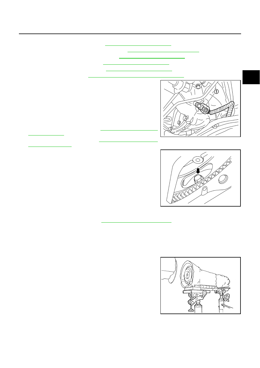
12. Remove crankshaft position sensor (POS) (1) from A/T assem-

bly.

CAUTION:

Do not subject it to impact by dropping or hitting it.

Do not disassemble.

Do not allow metal filings, etc., to get on the sensor's
front edge magnetic area.

Do not place in an area affected by magnetism.

13. Remove starter motor. Refer to 

SC-15, "VQ35DE ENGINE

MODELS (AWD)"

 .

14. Remove rear plate cover. Refer to 

EM-38, "Removal and Instal-

lation (AWD Models)"

 .

15. Turn crankshaft, and remove the four tightening bolts for drive

plate and torque converter.

CAUTION:

When turning the crankshaft, turn it clockwise as viewed
from the front of the engine.

16. Support A/T assembly with a transmission jack.

CAUTION:

When setting the transmission jack, be careful not to allow
it to collide against the drain plug.

17. Remove rear engine mounting member with power tool.
18. Remove engine mounting insulator (rear).

19. Disconnect A/T assembly harness connector.

20. Remove air breather hose. Refer to 

AT-272, "Removal and Installation"

 .

21. Remove A/T fluid charging pipe from A/T assembly.

22. Remove O-ring from A/T fluid charging pipe.

23. Disconnect fluid cooler tube from the A/T assembly.
24. Plug up openings such as the A/T fluid charging pipe hole, etc.

25. Remove bolts fixing A/T assembly to engine assembly with power tool.

26. Remove A/T assembly with transfer assembly from vehicle.

CAUTION:

Secure torque converter to prevent it from dropping.

Secure A/T assembly to a transmission jack.

27. Remove transfer assembly from A/T assembly with power tool.

SCIA6506J

LCIA0335E

SCIA2203E

AT-280

TRANSMISSION ASSEMBLY

INSPECTION
Installation and Inspection of Torque Converter

After inserting a torque converter to a A/T, be sure to check dis-
tance “A” to ensure it is within the reference value limit.

INSTALLATION

Install the removed parts in the reverse order of the removal, while paying attention to the following work.

When installing A/T assembly to the engine assembly, attach the
fixing bolts in accordance with the following standard.

Align the positions of tightening bolts for drive plate with those of
the torque converter, and temporarily tighten the bolts. Then,
tighten the bolts with the specified torque. Refer to 

AT-278,

"COMPONENTS"

 .

CAUTION:

When turning crankshaft, turn it clockwise as viewed from
the front of the engine.

When tightening the tightening bolts for the torque con-
verter after fixing the crankshaft pulley bolts, be sure to
confirm the tightening torque of the crankshaft pulley
mounting bolts. Refer to 

EM-74, "INSTALLATION"

 .

After converter is installed to drive plate, rotate crankshaft
several turns and check to be sure that A/T rotates freely without binding.

Install crankshaft position sensor (POS). Refer to 

EM-38, "Removal and Installation (AWD Models)"

 .

After completing installation, check A/T fluid leakage, A/T fluid level and A/T position. Refer to 

AT-13,

"Checking A/T Fluid"

 , 

AT-228, "Checking of A/T Position"

 .

Distance “A”:

25.0 mm (0.98 in) or more

SCIA5694E

Bolt No.

1

2

3

4

Number of bolts

1

5

2

1

Bolt length

 “

”mm (in)

55 (2.17)

65 (2.56)

35 (1.38)

40 (1.57)

Tightening torque
N·m (kg-m, ft-lb)

75

(7.7, 55)

47

(4.8, 35)

34

(3.5, 25)

SCIA4600E

SCIA2288E

OVERHAUL

AT-281

D

E

F

G

H

I

J

K

L

M

A

B

AT

OVERHAUL

PFP:00000

Components

NCS001R0

VQ35DE models

SCIA7983E

AT-282

OVERHAUL

1.

O-ring

2.

Oil pump cover

3.

O-ring

4.

Oil pump housing

5.

Self-sealing bolt

6.

Torque converter

7.

Converter housing

8.

Oil pump housing oil seal

9.

Bearing race

10.

Needle bearing

11.

O-ring

12.

Front carrier assembly

13.

Needle bearing

14.

Snap ring

15.

Front sun gear

16.

Snap ring

17.

Bearing race

18.

Needle bearing

19.

3rd one-way clutch

20.

Seal ring

21.

Input clutch assembly

22.

Needle bearing

23.

Rear internal gear

24.

Brake band

25.

Mid carrier assembly

26.

Needle bearing 

27.

Bearing race

28.

Rear carrier assembly

29.

Needle bearing 

30.

Mid sun gear

31.

Seal ring

32.

Rear sun gear

33.

1st one-way clutch

34.

Snap ring

35.

Needle bearing

36.

High and low reverse clutch hub

37.

Snap ring

38.

Bearing race

39.

Needle bearing

Refer to GI section to make sure icons (symbol marks) in the figure. Refer to 

GI-11, "Components"

 .

However, refer to the following symbols for others.

:

Apply Genuine RTV silicone sealant or equivalent. Refer to 

GI-47, "Recommended Chemical Products and Sealants"

 .


Content   ..  87  88  89  90   ..