Infiniti M35/M45 Y50. Manual - part 88
TRANSMISSION ASSEMBLY
AT-275
D
E
F
G
H
I
J
K
L
M
A
B
AT
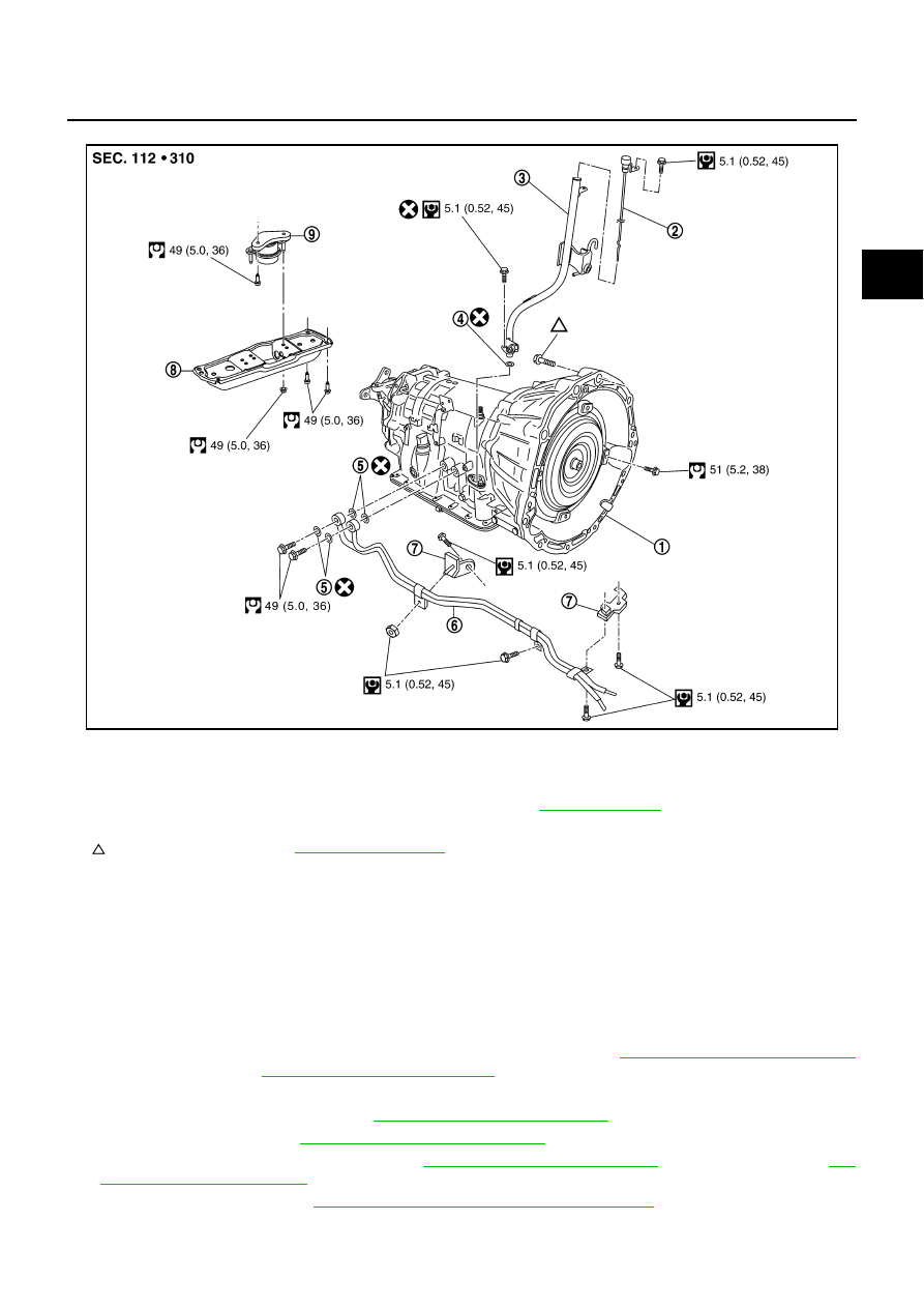
VK45DE models
REMOVAL
CAUTION:
●
When removing the A/T assembly from engine, first remove the crankshaft position sensor (POS)
from the A/T assembly.
●
Be careful not to damage sensor edge.
1.
Disconnect the battery cable from the negative terminal.
2.
Remove engine under cover with power tool.
3.
Remove A/T fluid level gauge.
4.
Remove exhaust front tube and center muffler with power tool. Refer to
EX-5, "Removal and Installation"
(for VQ35DE engine),
EX-7, "Removal and installation"
(for VK45DE engine).
5.
Remove heat insulator.
6.
Remove rear propeller shaft. Refer to
PR-8, "Removal and Installation"
.
7.
Remove rack stay. Refer to
FSU-9, "Removal and Installation"
.
8.
Remove exhaust mounting bracket. Refer to
EX-5, "Removal and Installation"
(for VQ35DE engine),
9.
Remove control rod. Refer to
AT-226, "Control Rod Removal and Installation"
SCIA7320E
1.
A/T assembly
2.
A/T fluid level gauge
3.
A/T fluid charging pipe
4.
O-ring
5.
Copper washer
6.
Fluid cooler tube
7.
Bracket
8.
Rear engine mounting member
9.
Engine mounting insulator (rear)
Refer to GI section to make sure icons (symbol marks) in the figure. Refer to
.
However, refer to following symbols for others.
: