Infiniti M35/M45 Y50. Manual - part 79


  Index      Infiniti     Infiniti M35/M45 Y50 - service repair manual 2007 year


Search            copyright infringement  


Content   ..  77  78  79  80   ..


Infiniti M35/M45 Y50. Manual - part 79


ON-VEHICLE SERVICE

AT-239

D

E

F

G

H

I

J

K

L

M

A

B

AT

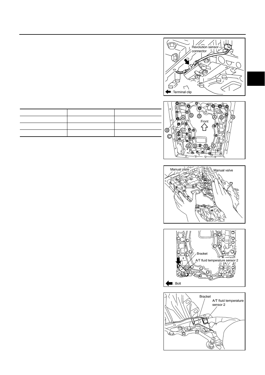
13. Straighten terminal clip to free revolution sensor harness.

14. Remove bolts A, B and C from control valve with TCM.

15. Remove control valve with TCM from transmission case.

CAUTION:

When removing, be careful with the manual valve notch and
manual plate height. Remove it vertically.

16. Remove A/T fluid temperature sensor 2 with bracket from con-

trol valve with TCM.

17. Remove bracket from A/T fluid temperature sensor 2.

SCIA7525E

Bolt symbol

Length mm (in)

Number of bolts

A

42 (1.65)

5

B

55 (2.17)

6

C

40 (1.57)

1

SCIA5139E

SCIA5142E

SCIA5301E

SCIA5264E

AT-240

ON-VEHICLE SERVICE

18. Remove O-ring from A/T assembly harness connector.

19. Disconnect TCM connectors.

CAUTION:

Be careful not to damage connectors.

20. Remove A/T assembly harness connector from control valve

with TCM using flat-blade screwdriver.

21. Disconnect TCM connector and park/neutral position switch

connector

CAUTION:

Be careful not to damage connectors.

Installation

CAUTION:

After completing installation, check A/T fluid leakage and A/T fluid level. Refer to 

AT-13, "Checking A/T

Fluid"

 .

SCIA5155E

SCIA5447E

SCIA5448E

SCIA5449E

ON-VEHICLE SERVICE

AT-241

D

E

F

G

H

I

J

K

L

M

A

B

AT

1.

Connect TCM connector and park/neutral position switch con-
nector.

2.

Install A/T assembly harness connector to control valve with
TCM.

3.

Connect TCM connectors.

4.

Install new O-ring in A/T assembly harness connector.

CAUTION:

Do not reuse O-ring.

Apply ATF to O-ring.

5.

Install A/T fluid temperature sensor 2 to bracket.

SCIA5449E

SCIA5450E

SCIA5447E

SCIA5155E

SCIA5264E

AT-242

ON-VEHICLE SERVICE

6.

Install A/T fluid temperature sensor 2 (with bracket) in control
valve with TCM. Tighten A/T fluid temperature sensor 2 bolt to
the specified torque. Refer to 

AT-236, "COMPONENTS"

 .

CAUTION:

Adjust bolt hole of bracket to bolt hole of control valve with
TCM.

7.

Install control valve with TCM in transmission case.

CAUTION:

Make sure that turbine revolution sensor securely installs
turbine revolution sensor hole.

Hang down revolution sensor harness toward outside so
as not to disturb installation of control valve with TCM.

Adjust A/T assembly harness connector of control valve
with TCM to terminal hole of transmission case.

Assemble it so that manual valve cutout is engaged with
manual plate projection.

8.

Install bolts A, B and C in control valve with TCM.

SCIA5301E

SCIA5034E

SCIA5142E

Bolt symbol

Length mm (in)

Number of bolts

A

42 (1.65)

5

B

55 (2.17)

6

C

40 (1.57)

1

SCIA5139E


Content   ..  77  78  79  80   ..