Infiniti M35/M45 Y50. Manual - part 62


  Index      Infiniti     Infiniti M35/M45 Y50 - service repair manual 2007 year


Search            copyright infringement  


Content   ..  60  61  62  63   ..


Infiniti M35/M45 Y50. Manual - part 62


DTC P1815 MANUAL MODE SWITCH

AT-171

D

E

F

G

H

I

J

K

L

M

A

B

AT

4. 

CHECK DTC

Perform “DTC Confirmation Procedure”. Refer to 

AT-167, "DTC Confirmation Procedure"

 .

OK or NG

OK

>> INSPECTION END

NG

>> GO TO 5.

5. 

CHECK TCM POWER SUPPLY AND GROUND CIRCUIT

Check TCM power supply and ground circuit. Refer to 

AT-180, "MAIN POWER SUPPLY AND GROUND CIR-

CUIT"

 .

OK or NG

OK

>> GO TO 6.

NG

>> Repair or replace damaged parts.

6. 

DETECT MALFUNCTIONING ITEM

Check the following.

The A/T assembly harness connector pin terminals for damage or loose connection with harness connec-
tor.

OK or NG

OK

>> Replace the control valve with TCM. Refer to 

AT-236, "Control Valve With TCM and A/T Fluid

Temperature Sensor 2"

 .

NG

>> Repair or replace damaged parts.

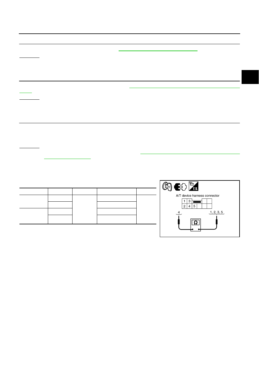
Component Inspection

NCS001P0

MANUAL MODE SWITCH

Check continuity between terminals.

Item

Position

Connector Terminal

Continuity

Manual mode 
select switch

Auto

M133

4 - 5

Yes

Manual

1 - 4

Manual mode 
position select 
switch

UP

3 - 4

DOWN

2 - 4

SCIA6860E

AT-172

DTC P1841 ATF PRESSURE SWITCH 1

DTC P1841 ATF PRESSURE SWITCH 1

PFP:25240

Description

NCS001P1

Fail-safe function to detect front brake solenoid valve condition.

CONSULT-II Reference Value

NCS001P2

On Board Diagnosis Logic

NCS001P3

This is not an OBD-II self-diagnostic item.

Diagnostic trouble code “P1841 ATF PRES SW 1/CIRC” with CONSULT-II is detected when TCM detects
that actual gear ratio is normal, and relation between gear position and condition of ATF pressure switch 1
is irregular during depressing accelerator pedal. (Other than during shift change.)

Possible Cause

NCS001P4

ATF pressure switch 1

Harness or connectors
(Switch circuit is open or shorted.)

DTC Confirmation Procedure

NCS001P5

CAUTION:

Always drive vehicle at a safe speed.

NOTE:
If “DTC Confirmation Procedure” has been previously performed, always turn ignition switch OFF and
wait at least 10 seconds before performing the next test.
After the repair, perform the following procedure to confirm the malfunction is eliminated.

 WITH CONSULT-II

1.

Start engine.

2.

Accelerate vehicle to maintain the following conditions.
ACCELE POSI: 1.5/8 - 2.0/8
SLCT LVR POSI: “D” position 
GEAR: “3” 

Þ

 “4” (FR/B ON/OFF)

Driving location: Driving the vehicle uphill (increased
engine load) will help maintain the driving conditions
required for this test.

3.

Perform step 2 again.

4.

Turn ignition switch OFF, then perform step 1 to 3 again.

5.

Check “SELF-DIAG RESULTS” mode for “A/T” with CONSULT-
II.
If DTC (P1841) is detected, go to 

AT-173, "Diagnostic Procedure"

 .

If DTC (P1757) is detected, go to 

AT-152, "Diagnostic Procedure"

 .

Item name

Condition

Display value

ATF PRES SW 1

Front brake engaged. Refer to 

AT-21


.

ON

Front brake disengaged. Refer to 

AT-21


.

OFF

BCIA0030E

DTC P1841 ATF PRESSURE SWITCH 1

AT-173

D

E

F

G

H

I

J

K

L

M

A

B

AT

Diagnostic Procedure

NCS001P6

1. 

CHECK INPUT SIGNAL

 With CONSULT-II

1.

Start engine.

2.

Select “ECU INPUT SIGNALS” or “MAIN SIGNALS” in “DATA
MONITOR” mode for “A/T” with CONSULT-II.

3.

Drive vehicle in the “D” position (3rd 

Þ

 4th gear), and confirm

the ON/OFF actuation of the “ATF PRES SW 1”.

OK or NG

OK

>> GO TO 4.

NG

>> GO TO 2.

2. 

CHECK TCM POWER SUPPLY AND GROUND CIRCUIT

Check TCM power supply and ground circuit. Refer to 

AT-180, "MAIN POWER SUPPLY AND GROUND CIR-

CUIT"

 .

OK or NG

OK

>> GO TO 3.

NG

>> Repair or replace damaged parts.

3. 

DETECT MALFUNCTIONING ITEM

Check the following.

The A/T assembly harness connector pin terminals for damage or loose connection with harness connec-
tor.

OK or NG

OK

>> Replace the control valve with TCM. Refer to 

AT-236, "Control Valve With TCM and A/T Fluid

Temperature Sensor 2"

 .

NG

>> Repair or replace damaged parts.

4. 

CHECK DTC

Perform “DTC Confirmation Procedure”. Refer to 

AT-172, "DTC Confirmation Procedure"

 .

OK or NG

OK

>> INSPECTION END

NG

>> GO TO 2.

Item name

Condition

Display value

ATF PRES SW 1

Front brake engaged. Refer to 

AT-21


.

ON

Front brake disengaged. Refer to 

AT-21


.

OFF

PCIA0067E

AT-174

DTC P1843 ATF PRESSURE SWITCH 3

DTC P1843 ATF PRESSURE SWITCH 3

PFP:25240

Description

NCS001P7

Fail-safe function to detect input clutch solenoid valve condition.

CONSULT-II Reference Value

NCS001P8

On Board Diagnosis Logic

NCS001P9

This is not an OBD-II self-diagnostic item.

Diagnostic trouble code “P1843 ATF PRES SW 3/CIRC” with CONSULT-II is detected when TCM detects
that actual gear ratio is normal, and relation between gear position and condition of ATF pressure switch 3
is irregular during depressing accelerator pedal. (Other than during shift change.)

Possible Cause

NCS001PA

ATF pressure switch 3

Harness or connectors
(Switch circuit is open or shorted.)

DTC Confirmation Procedure

NCS001PB

CAUTION:

Always drive vehicle at a safe speed.

NOTE:
If “DTC Confirmation Procedure” has been previously performed, always turn ignition switch OFF and
wait at least 10 seconds before performing the next test.
After the repair, perform the following procedure to confirm the malfunction is eliminated.

 WITH CONSULT-II

1.

Start engine.

2.

Accelerate vehicle to maintain the following conditions.
ACCELE POSI: 1.5/8 - 2.0/8
SLCT LVR POSI: “D” position 
GEAR: “3” 

Þ

 “4” (I/C ON/OFF) 

Driving location: Driving the vehicle uphill (increased
engine load) will help maintain the driving conditions
required for this test.

3.

Perform step 2 again.

4.

Turn ignition switch OFF, then perform step 1 to 3 again.

5.

Check “SELF-DIAG RESULTS” mode for “A/T” with CONSULT-
II.
If DTC (P1843) is detected, go to 

AT-175, "Diagnostic Procedure"

 .

If DTC (P1752) is detected, go to 

AT-148, "Diagnostic Procedure"

 .

Item name

Condition

Display value

ATF PRES SW 3

Input clutch engaged. Refer to 

AT-21


.

ON

Input clutch disengaged. Refer to 

AT-21


.

OFF

BCIA0030E


Content   ..  60  61  62  63   ..