Infiniti M35/M45 Y50. Manual - part 24


  Index      Infiniti     Infiniti M35/M45 Y50 - service repair manual 2007 year


Search            copyright infringement  


Content   ..  22  23  24  25   ..


Infiniti M35/M45 Y50. Manual - part 24


A/T CONTROL SYSTEM

AT-19

D

E

F

G

H

I

J

K

L

M

A

B

AT

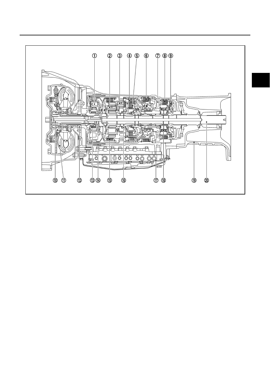
Cross-Sectional View (AWD Models)

NCS001JN

1.

Front planetary gear

2.

Mid planetary gear

3.

Rear planetary gear

4.

Direct clutch

5.

High and low reverse clutch

6.

Reverse brake

7.

Drum support

8.

Forward brake

9.

Low coast brake

10. Input shaft

11.

Torque converter

12. Oil pump

13. 3rd one-way clutch

14.

Front brake

15. Input clutch

16. 1st one-way clutch

17.

Control valve with TCM

18. Forward one-way clutch

19. Adapter case

20.

Output shaft

SCIA6947E

AT-20

A/T CONTROL SYSTEM

Shift Mechanism

NCS001JO

The A/T uses compact triple planetary gear systems to improve power transmission efficiency, simplify con-
struction and reduce weight.
It also employs an optimum shift control and super wide gear ratios. They improve starting performance and
acceleration during medium and high-speed operation.

CONSTRUCTION 

FUNCTION OF CLUTCH AND BRAKE 

1.

Front brake

2.

Input clutch

3.

Direct clutch

4.

High and low reverse clutch

5.

Reverse brake

6.

Forward brake

7.

Low coast brake

8.

1st one-way clutch

9.

Forward one-way clutch

10. 3rd one-way clutch

11.

Front sun gear

12. Input shaft

13. Mid internal gear

14.

Front internal gear

15. Rear carrier

16. Rear sun gear

17.

Mid sun gear

18. Front carrier

19. Mid carrier

20.

Rear internal gear

21. Output shaft

22. Parking gear

23.

Parking pawl

PCIA0002J

Name of the Part

Abbreviation

Function

Front brake (1)

FR/B

Fastens the front sun gear (11).

Input clutch (2)

I/C

Connects the input shaft (12), the front internal gear (14) and the mid internal 
gear (13).

Direct clutch (3)

D/C

Connects the rear carrier (15) and the rear sun gear (16).

High and low reverse clutch (4)

HLR/C

Connects the mid sun gear (17) and the rear sun gear (16).

Reverse brake (5)

R/B

Fastens the rear carrier (15).

Forward brake (6)

Fwd/B

Fastens the mid sun gear (17).

Low coast brake (7) 

LC/B

Fastens the mid sun gear (17).

1st one-way clutch (8)

1st OWC

Allows the rear sun gear (16) to turn freely forward relative to the mid sun gear 
(17) but fastens it for reverse rotation.

Forward one-way clutch (9)

Fwd OWC

Allows the mid sun gear (17) to turn freely in the forward direction but fastens it 
for reverse rotation.

3rd one-way clutch (10)

3rd OWC

Allows the front sun gear (11) to turn freely in the forward direction but fastens 
it for reverse rotation.

A/T CONTROL SYSTEM

AT-21

D

E

F

G

H

I

J

K

L

M

A

B

AT

CLUTCH AND BAND CHART

SCIA6962E

AT-22

A/T CONTROL SYSTEM

POWER TRANSMISSION 
“N” Position

Since both the forward brake and the reverse brake are released, torque from the input shaft drive is not trans-
mitted to the output shaft.

“P” Position

The same as for the “N” position, both the forward brake and the reverse brake are released, so torque
from the input shaft drive is not transmitted to the output shaft.

The parking pawl linked with the selector lever meshes with the parking gear and fastens the output shaft
mechanically.

1.

Front brake

2.

Input clutch

3.

Direct clutch

4.

High and low reverse clutch

5.

Reverse brake

6.

Forward brake

7.

Low coast brake

8.

1st one-way clutch

9.

Forward one-way clutch

10. 3rd one-way clutch

11.

Front sun gear

12. Input shaft

13. Mid internal gear

14. Front internal gear

15. Rear carrier

16. Rear sun gear

17. Mid sun gear

18. Front carrier

19. Mid carrier

20. Rear internal gear

21. Output shaft

22. Parking gear

23. Parking pawl

PCIA0003J


Content   ..  22  23  24  25   ..