Infiniti M35/M45 Y50. Manual - part 14


  Index      Infiniti     Infiniti M35/M45 Y50 - service repair manual 2007 year


Search            copyright infringement  


Content   ..  12  13  14  15   ..


Infiniti M35/M45 Y50. Manual - part 14


TROUBLE DIAGNOSIS FOR SELF-DIAGNOSTIC ITEMS

ACS-49

[ICC]

C

D

E

F

G

H

I

J

L

M

A

B

ACS

4. 

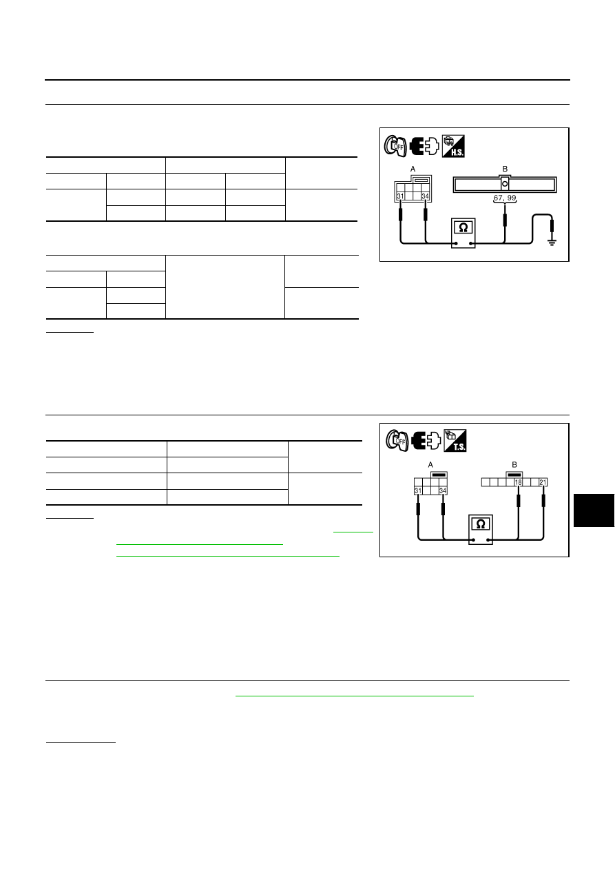
CHECK ICC STEERING SWITCH SIGNAL CIRCUIT

1.

Disconnect spiral cable connector and ECM connector.

2.

Check continuity between spiral cable harness connector (A)
and ECM harness connector (B). 

3.

Check continuity between spiral cable harness connector (A)
and ground. 

OK or NG

OK

>> GO TO 5.

NG

>> 1. Repair or replace harness between spiral cable and ECM.

2. Erase DTC and perform ICC system running test. Then perform self-diagnosis of ICC system

again.

5. 

CHECK COMBINATION SWITCH (SPIRAL CABLE)

Check continuity between spiral cable terminals. 

OK or NG

OK

>> 1. Perform “ENGINE” self-diagnosis. Refer to 

EC-123,

"CONSULT-II Function (ENGINE)"

  (for VQ35DE) or

EC-826, "CONSULT-II Function (ENGINE)"

    (for

VK45DE).

2. After repairing or replacing applicable item, erase DTC and perform ICC system running test.

Then perform self-diagnosis of ICC system again.

NG

>> 1. Replace spiral cable.

2. Erase DTC and perform ICC system running test. Then perform self-diagnosis of ICC system

again.

DTC 12 LASER BEAM OFFCNTR

NKS004D6

1. 

ADJUST LASER BEAM AIMING

1.

Adjust laser beam aiming. Refer to 

ACS-15, "LASER BEAM AIMING ADJUSTMENT"

2.

Erase DTC and perform ICC system running test. Then perform self-diagnosis of ICC system again.

3.

Check if “LASER BEAM OFFCNTR [C1A12]” (DTC 12) is indicated in self-diagnosis item in the display.

Is it indicated?

YES

>> 1. Replace ICC sensor integrated unit, and adjust laser beam aiming.

2. Erase DTC and perform ICC system running test. Then perform self-diagnosis of ICC system

again.

NO

>> INSPECTION END

A

B

Continuity

Connector

Terminal Connector

Terminal 

M39

31

F108

67

Yes

34

M71

99

A

Ground

Continuity

Connector

Terminal 

M39

31

No

34

PKIB9339E

A

B

Continuity

Terminal Terminal 

31

18

Yes

34

21

PKIB9340E

ACS-50

[ICC]

TROUBLE DIAGNOSIS FOR SELF-DIAGNOSTIC ITEMS

DTC 13 STOP LAMP RLY FIX

NKS004D7

1. 

PERFORM ICC SENSOR INTEGRATED UNIT SELF-DIAGNOSIS

1.

Perform self-diagnosis.

2.

Check if “CAN COMM CIRCUIT [U1000]” (DTC 100) other than “STOP LAMP RLY FIX [C1A13]” (DTC 13)
is indicated in self-diagnosis item in the display.

Is it indicated?

YES

>> 1. CAN communication inspection. Refer to 

ACS-61, "DTC 100 CAN COMM CIRCUIT"

 .

2. After repairing or replacing applicable item, erase DTC and perform ICC system running test.

Then perform self-diagnosis of ICC system again.

NO

>> GO TO 2.

2. 

CHECK CONNECTOR FOR ECM

1.

Turn ignition switch OFF.

2.

Disconnect ECM connector, and connect it securely again. 

3.

Erase DTC and perform ICC system running test. Then perform self-diagnosis of ICC system again.

4.

Check if “STOP LAMP RLY FIX [C1A13]” (DTC 13) is indicated in self-diagnosis item in the display.

Is it indicated?

YES

>> GO TO 3.

NO

>> Poor connector connection

1. Check connector. (Check connector housing for disconnected, loose, bent, and collapsed ter-

minals. If any malfunction is detected, repair applicable part.)

2. Erase DTC and perform ICC system running test. Then perform self-diagnosis of ICC system

again.

3. 

CHECK STOP LAMP SWITCH WITH ICC DATA MONITOR

 With CONSULT-II

With “ICC” “DATA MONITOR”, check if “STOP LAMP SW” operates normally. 

OK or NG

OK

>> GO TO 11.

NG

>> GO TO 4.

4. 

CHECK STOP LAMP SWITCH INSTALLATION AND ADJUSTMENT 

Check stop lamp switch for proper installation, and adjust the switch if necessary. Refer to 

BR-6, "BRAKE

PEDAL"

 .

OK or NG

OK

>> GO TO 5.

NG

>> 1. Adjust stop lamp switch.

2. Erase DTC and perform ICC system running test. Then perform self-diagnosis of ICC system

again.

5. 

CHECK STOP LAMP SWITCH

Check stop lamp switch. Refer to 

ACS-69, "ICC Brake Switch and Stop Lamp Switch"

 .

OK or NG

OK

>> GO TO 6.

NG

>> 1. Replace stop lamp switch.

2. Erase DTC and perform ICC system running test. Then perform self-diagnosis of ICC system

again.

TROUBLE DIAGNOSIS FOR SELF-DIAGNOSTIC ITEMS

ACS-51

[ICC]

C

D

E

F

G

H

I

J

L

M

A

B

ACS

6. 

CHECK STOP LAMP ILLUMINATION

1.

Turn ignition switch OFF.

2.

Disconnect ICC brake hold relay.

3.

Connect stop lamp switch connector.

4.

Check if stop lamp is turned ON when depressing brake pedal.

OK or NG

OK

>> GO TO 7.

NG

>> 1. Repair or replace stop lamp circuit.

2. Erase DTC and perform ICC system running test. Then perform self-diagnosis of ICC system

again.

7. 

CHECK HARNESS BETWEEN STOP LAMP SWITCH AND ECM

1.

Disconnect stop lamp switch connector and ECM connector.

2.

Check continuity between stop lamp switch harness connector
(A) and ECM harness connector (B).

3.

Check continuity between stop lamp switch harness connector
(A) and ground.

OK or NG

OK

>> GO TO 8.

NG

>> 1. Repair or replace harness between stop lamp switch and ECM.

2. Erase DTC and perform ICC system running test. Then perform self-diagnosis of ICC system

again.

8. 

CHECK ICC BRAKE HOLD RELAY CIRCUIT 

1.

Connect ICC brake hold relay and ECM connector.

2.

When brake pedal is not depressed, make sure that stop lamp does not illuminate.

OK or NG

OK

>> GO TO 10.

NG

>> GO TO 9.

9. 

CHECK ICC BRAKE HOLD RELAY 

1.

Disconnect ICC brake hold relay.

2.

Check ICC brake hold relay. Refer to 

ACS-69, "ICC Brake Hold Relay"

 .

OK or NG

OK

>> GO TO 10.

NG

>> 1. Replace ICC brake hold relay.

2. Erase DTC and perform ICC system running test. Then perform self-diagnosis of ICC system

again.

A

B

Continuity

Connector

Terminal Connector

Terminal

E124

2

M71

101

Yes

A

Ground

Continuity

Connector

Terminal 

E124

2

No

PKIC0927E

ACS-52

[ICC]

TROUBLE DIAGNOSIS FOR SELF-DIAGNOSTIC ITEMS

10. 

PERFORM ECM SELF-DIAGNOSIS

 With CONSULT-II

1.

Perform “ENGINE” self-diagnosis. Refer to 

EC-123, "CONSULT-II Function (ENGINE)"

  (for VQ35DE) or

EC-826, "CONSULT-II Function (ENGINE)"

  (for VK45DE).

2.

Check if malfunction is indicated.

Is malfunction indicated?

YES

>> 1. Repair or replace applicable item.

2. Erase DTC and perform ICC system running test. Then perform self-diagnosis of ICC system

again.

NO

>> 1. Replace ICC sensor integrated unit, and adjust laser beam aiming.

2. Erase DTC and perform ICC system running test. Then perform self-diagnosis of ICC system

again.

11. 

CHECK HARNESS BETWEEN ICC SENSOR INTEGRATED UNIT AND ICC BRAKE HOLD RELAY

1.

Turn ignition switch OFF.

2.

Disconnect ICC sensor integrated unit connector and ICC brake hold relay.

3.

Check continuity between ICC sensor integrated unit harness
connector (A) and ICC brake hold relay harness connector (B).

4.

Check continuity between ICC sensor integrated unit harness
connector (A) and ground.

OK or NG

OK

>> GO TO 12.

NG

>> 1. Repair harness between ICC sensor integrated unit and ICC brake hold relay.

2. Erase DTC and perform ICC system running test. Then perform self-diagnosis of ICC system

again.

12. 

CHECK ICC BRAKE HOLD RELAY GROUND CIRCUIT 

Check continuity between ICC brake hold relay harness connector
and ground.

OK or NG

OK

>> GO TO 13.

NG

>> 1. Repair or replace harness between ICC brake hold

relay and ground.

2. Erase DTC and perform ICC system running test.

Then perform self-diagnosis of ICC system again.

A

B

Continuity

Connector

Terminal Connector

Terminal 

E61

2

E80

2

Yes

A

Ground

Continuity

Connector

Terminal

E61

2

No

PKIB9338E

ICC brake hold relay 
connector

Terminal

Ground

Continuity

E80

1

Yes

PKIB9341E


Content   ..  12  13  14  15   ..