Infiniti F50. Manual - part 827
TROUBLE DIAGNOSIS FOR SYMPTOMS
WT-23
C
D
F
G
H
I
J
K
L
M
A
B
WT
Inspection 2: Warning Lamp Stays On When Ignition Switch Is Turned On.
EES000DM
DIAGNOSTIC PROCEDURE
1.
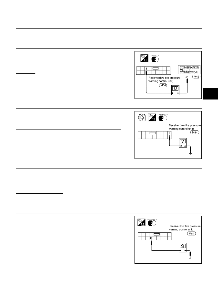
CHECK CIRCUIT
●
Disconnect combination meter connector M43.
●
Check continuity between low tire pressure warning control unit
connector (body side) terminal No.3 and combination meter con-
nector (body side) terminal No.54.
OK or NG?
OK
>> GO TO 2.
NG
>> Repair or replace harness connector.
2.
CHECK POWER SUPPLY CIRCUIT
●
Check voltage between low tire pressure warning control unit
terminal No.1 and ground.
●
Carry out self-diagnosis again.
Does battery voltage exit when ignition switch is turned “ON”?
YES
>> GO TO 3.
NO
>> Repair or replace power supply harness connector.
3.
CHECK POWER SUPPLY CIRCUIT
1.
Ignition switch is turned "ON".
2.
Check voltage between low tire pressure warning control unit terminal 2 and ground.
Does battery voltage exist?
YES
>> GO TO 4.
NO
>> Repair or replace harness connector.
4.
CHECK GROUND CIRCUIT
●
Check continuity between low tire pressure warning control unit
terminal No.11 and ground.
●
Carry out self-diagnosis again.
Does continuity exist?
YES
>> Replace low tire pressure warning control unit.
NO
>> Repair or replace ground circuit harness connector.
SEIA0060E
SEIA0058E
2 - Ground:
Battery voltage
SEIA0057E