Infiniti F50. Manual - part 809


  Index      Infiniti     Infiniti F50 - service repair manual 2006 year


Search            


Content   ..  807  808  809  810   ..


Infiniti F50. Manual - part 809


TROUBLE DIAGNOSIS

SRS-23

C

D

E

F

G

I

J

K

L

M

A

B

SRS

7.

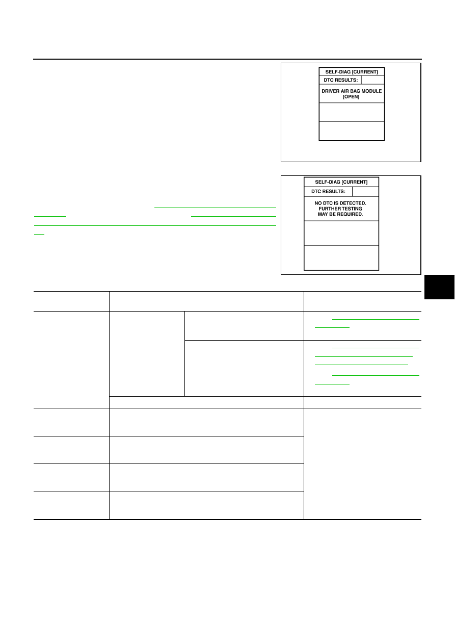
Diagnostic code is displayed on “SELF-DIAG [CURRENT]”.

If no malfunction is detected on “SELF-DIAG [CURRENT]” even
though malfunction is detected in “SRS Operation Check”, check the
battery voltage. If the battery voltage is less than 9V, charge or
replace the battery. Then go to 

SRS-26, "DIAGNOSTIC PROCE-

DURE 3"

 . If the battery voltage is OK, go to 

SRS-28, "DIAGNOSTIC

PROCEDURE 4 (CONTINUED FROM DIAGNOSTIC PROCEDURE
2)"

  to diagnose the following cases:

Self-diagnostic result “SELF-DIAG [PAST]” (previously stored in
the memory) might not be erased after repair.

The SRS system malfunctions intermittently.

CONSULT-II Diagnostic Code Chart ("SELF-DIAG [CURRENT]")

SHIA0203E

SRS701

Diagnostic item

Explanation

Repair order

“Recheck SRS at each replacement”

NO DTC IS 
DETECTED.

When malfunction is 
indicated by the “AIR 
BAG” warning lamp in 
User mode.

Low battery voltage (Less than 9V)

Go to 

SRS-22, "DIAGNOSTIC PRO-

CEDURE 2"

  after charging the bat-

tery.

Self-diagnostic result “SELF-DIAG 
[PAST]” (previously stored in the 
memory) might not be erased after 
repair.

Intermittent malfunction has been 
detected in the past.

Go to 

SRS-28, "DIAGNOSTIC PRO-

CEDURE 4 (CONTINUED FROM 
DIAGNOSTIC PROCEDURE 2)"

 .

Go to 

SRS-28, "DIAGNOSTIC PRO-

CEDURE 5"

 .

No malfunction is detected.

DRIVER AIRBAG 
MODULE
[OPEN]

Driver air bag module circuit is open (including the spiral cable).

1. Visually check the wiring harness 

connection.

2. Replace the harness if it has visible 

damage.

3. Replace driver air bag module. 

(Before disposal, it must be 
deployed.)

4. Replace the spiral cable.

5. Replace the diagnosis sensor unit.

6. Replace the related harness.

DRIVER AIRBAG 
MODULE
[VB-SHORT]

Driver air bag module circuit is shorted to a power supply circuit 
(including the spiral cable).

DRIVER AIRBAG 
MODULE
[GND-SHORT]

Driver air bag module circuit is shorted to ground (including the 
spiral cable).

DRIVER AIRBAG 
MODULE
[SHORT]

Driver air bag module circuit is shorted between lines.

SRS-24

TROUBLE DIAGNOSIS

ASSIST A/B MODULE
[OPEN]

Front passenger air bag module circuit is open.

1. Visually check the wiring harness 

connection.

2. Replace the harness if it has visible 

damage.

3. Replace front passenger air bag 

module. (Before disposal of it, it 
must be deployed.)

4. Replace the diagnosis sensor unit.

5. Replace the related harness.

ASSIST A/B MODULE
[VB-SHORT]

Front passenger air bag module circuit is shorted to a power-
supply.

ASSIST A/B MODULE
[GND-SHORT]

Front passenger air bag module circuit is shorted to ground.

ASSIST A/B MODULE
[SHORT]

Front passenger air bag module circuit is shorted between lines.

CRASH ZONE SEN
[UNIT FAIL]
CRASH ZONE SEN
[COMM FAIL]

Crash zone sensor

1. Visually check the wiring harness 

connection.

2. Replace the harness if it has visible 

damage.

3. Replace the crash zone sensor.

4. Replace the diagnosis sensor unit.

5. Replace the related harness.

SIDE MODULE LH
[OPEN]

Front LH side air bag module circuit is open.

1. Visually check the wiring harness 

connection.

2. Replace the harness if it has visible 

damage.

3. Replace front LH setback assembly 

(Front LH side air bag module).
(Before disposal, it must be 
deployed.)

4. Replace the diagnosis sensor unit.

5. Replace the related harness.

SIDE MODULE LH
[VB-SHORT]

Front LH side air bag module circuit is shorted to a power sup-
ply circuit.

SIDE MODULE LH
[GND-SHORT]

Front LH side air bag module circuit is shorted to ground.

SIDE MODULE LH
[SHORT]

Front LH side air bag module circuit is shorted between lines.

SIDE MODULE RH
[OPEN]

Front RH side air bag module circuit is open.

1. Visually check the wiring harness 

connection.

2. Replace the harness if it has visible 

damage.

3. Replace front RH setback assembly 

(Front RH side air bag module).
(Before disposal, it must be 
deployed.)

4. Replace the diagnosis sensor unit.

5. Replace the related harness.

SIDE MODULE RH
[VB-SHORT]

Front RH side air bag module circuit is shorted to a power sup-
ply circuit.

SIDE MODULE RH
[GND-SHORT]

Front RH side air bag module circuit is shorted to ground.

SIDE MODULE RH
[SHORT]

Front RH side air bag module circuit is shorted between lines.

SATELLITE SENS LH
[UNIT FAIL]
SATELLITE SENS LH
[COMM FAIL]

LH side air bag (Satellite) sensor

1. Visually check the wiring harness 

connection.

2. Replace the harness if it has visible 

damage.

3. Replace the LH side air bag (Satel-

lite) sensor.

4. Replace the diagnosis sensor unit.

5. Replace the related harness.

SATELLITE SENS RH
[UNIT FAIL]
SATELLITE SENS RH
[COMM FAIL]

RH side air bag (Satellite) sensor

1. Visually check the wiring harness 

connection.

2. Replace the harness if it has visible 

damage.

3. Replace the RH side air bag (Satel-

lite) sensor.

4. Replace the diagnosis sensor unit.

5. Replace the related harness.

Diagnostic item

Explanation

Repair order

“Recheck SRS at each replacement”

TROUBLE DIAGNOSIS

SRS-25

C

D

E

F

G

I

J

K

L

M

A

B

SRS

NOTE:

Follow the procedures in numerical order when repairing malfunctioning parts. Confirm whether malfunc-
tion is eliminated using air bag warning lamp or CONSULT-II each time repair is finished. If malfunction is
still observed, proceed to the next step. When malfunction is eliminated, further repair work is not
required.

PRE-TEN FRONT LH
[OPEN]

Front LH pre-tensioner circuit is open. 

1. Visually check the wiring harness 

connections.

2. Replace the harness if it has visible 

damage.

3. Replace front LH seat belt.

(Before disposal, it must be acti-
vated.)

4. Replace the diagnosis sensor unit.

5. Replace the related harness.

PRE-TEN FRONT LH
[VB-SHORT]

Front LH pre-tensioner circuit is shorted to a power supply cir-
cuit.

PRE-TEN FRONT LH
[GND-SHORT]

Front LH pre-tensioner circuit is shorted to ground.

PRE-TEN FRONT LH
[SHORT]

Front LH pre-tensioner circuit is shorted between lines.

PRE-TEN FRONT RH
[OPEN]

Front RH pre-tensioner circuit is open.

1. Visually check the wiring harness 

connections.

2. Replace the harness if it has visible 

damage.

3. Replace front RH seat belt.

(Before disposal, it must be acti-
vated.)

4. Replace the diagnosis sensor unit.

5. Replace the related harness.

PRE-TEN FRONT RH
[VB-SHORT]

Front RH pre-tensioner circuit is shorted to a power supply cir-
cuit.

PRE-TEN FRONT RH
[GND-SHORT]

Front RH pre-tensioner circuit is shorted to ground.

PRE-TEN FRONT RH
[SHORT]

Front RH pre-tensioner circuit is shorted between lines.

CURTAIN MODULE LH
[OPEN]

LH side curtain air bag module circuit is open.

1. Visually check the wiring harness 

connection.

2. Replace the harness if it has visible 

damage.

3. Replace LH side curtain air bag 

module.
(Before disposal, it must be 
deployed.)

4. Replace the diagnosis sensor unit.

5. Replace the related harness.

CURTAIN MODULE LH
[VB-SHORT]

LH side curtain air bag module circuit is shorted to a power sup-
ply circuits.

CURTAIN MODULE LH
[GND-SHORT]

LH side curtain air bag module circuit is shorted to ground.

CURTAIN MODULE LH
[SHORT]

LH side curtain air bag module circuit is shorted between lines.

CURTAIN MODULE RH
[OPEN]

RH side curtain air bag module circuit is open.

1. Visually check the wiring harness 

connection.

2. Replace the harness if it has visible 

damage.

3. Replace RH side curtain air bag 

module.
(Before disposal, it must be 
deployed.)

4. Replace the diagnosis sensor unit.

5. Replace the related harness.

CURTAIN MODULE RH
[VB-SHORT]

RH side curtain air bag module circuit is shorted to a power sup-
ply circuit.

CURTAIN MODULE RH
[GND-SHORT]

RH side curtain air bag module circuit is shorted to ground.

CURTAIN MODULE RH
[SHORT]

RH side curtain air bag module circuit is shorted between lines.

CONTROL UNIT

Diagnosis sensor unit is malfunctioning.

1. Visually check the wiring harness 

connection.

2. Replace the diagnosis sensor unit.

Diagnostic item

Explanation

Repair order

“Recheck SRS at each replacement”

SRS-26

TROUBLE DIAGNOSIS

DIAGNOSTIC PROCEDURE 3

Final checking after repairing SRS by using CONSULT-II — Diagnosis mode

1.

After repairing SRS, connect both battery cables.

2.

Connect CONSULT-II and CONSULT-II CONVERTER to data
link connector.

3.

Turn ignition switch ON.

4.

Touch “START(NISSAN BASED VHCL)”.

5.

Touch “AIR BAG”.

6.

Touch “SELF-DIAG [CURRENT]”.

SHIA0179E

PHIA0157E

SRS771

SRS697


Content   ..  807  808  809  810   ..