Infiniti F50. Manual - part 775
AUTOMATIC DRIVE POSITIONER
SE-91
C
D
E
F
G
H
J
K
L
M
A
B
SE
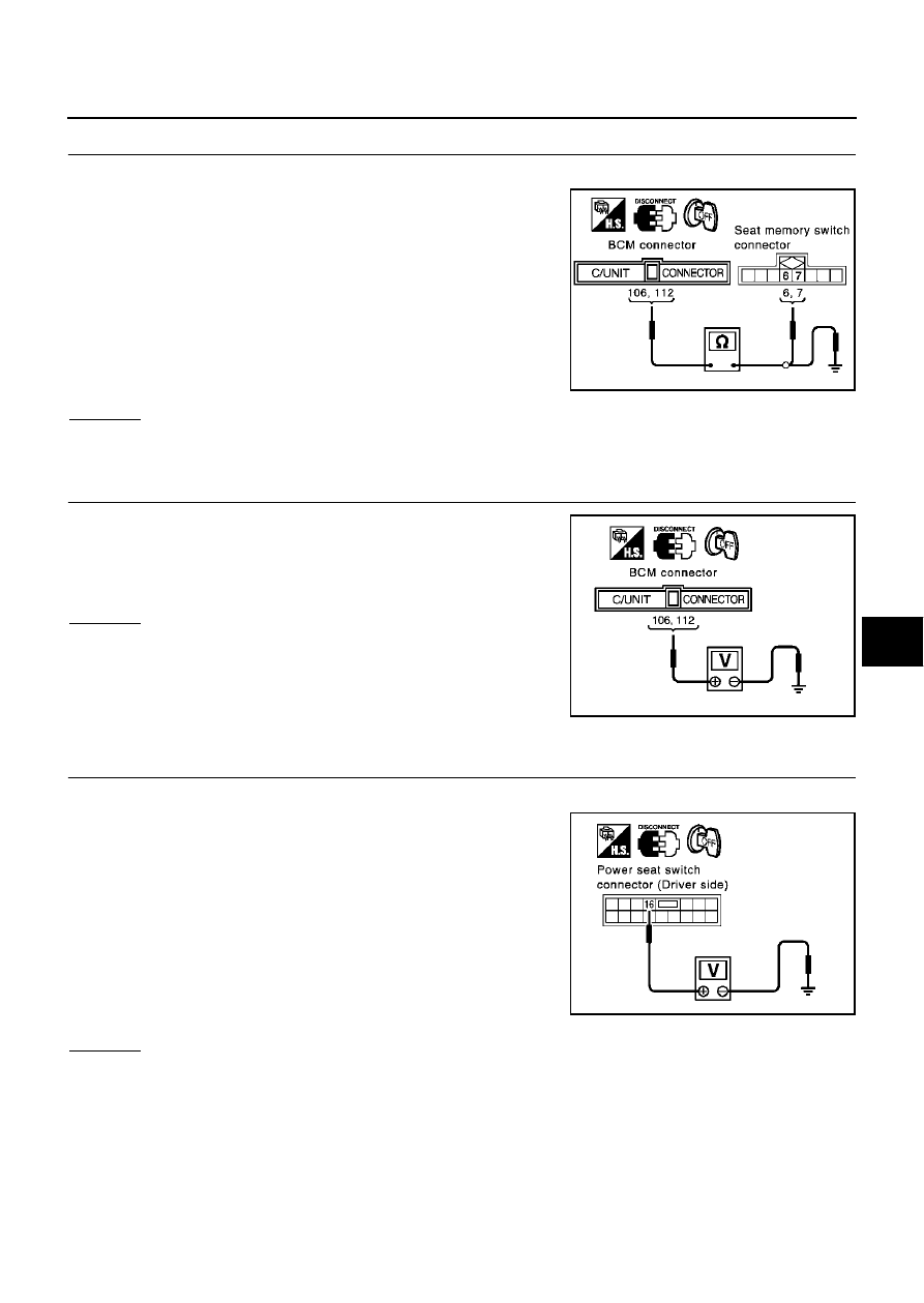
4.
CHECK HARNESS CONTINUITY
1.
Disconnect BCM connector.
2.
Check continuity between BCM connector M4 terminals 106
(BR/Y), 112 (L/W) and seat memory switch connector D3 termi-
nals 6 (BR/Y), 7 (L/W).
3.
Check continuity between BCM connector M4 terminals 106
(BR/Y), 112 (L/W) and ground.
OK or NG
OK
>> GO TO 5.
NG
>> Repair or replace harness between BCM and memory switch.
5.
CHECK SEAT MEMORY SWITCH INDICATOR SIGNAL
Check voltage between BCM connector M4 terminals 106 (BR/Y),
112 (L/W) and ground.
OK or NG
OK
>> Replace BCM.
NG
>> Replace seat memory switch.
Lumber Support Circuit Inspection
EIS0042B
1.
CHECK LUMBER SUPPORT SWITCH
1.
Turn ignition switch OFF.
2.
Disconnect front power seat switch (driver side) connector.
3.
Check voltage between power seat switch (driver side) connec-
tor B144 terminal 16 (R) and ground.
OK or NG
OK
>> GO TO 2.
NG
>> Repair or replace harness between fuse block (J/B) and power seat switch (Driver side).
106 (BR/Y) – 6 (BR/Y)
: Continuity should exist.
112 (L/W) – 7 (L/W)
: Continuity should exist.
106 (BR/Y) – Ground
: Continuity should not exist.
112 (L/W) – Ground
: Continuity should not exist.
PIIA4373E
106 (BR/Y) – Ground
: Battery voltage.
112 (L/W) – Ground
: Battery voltage.
PIIA3313E
16 (R) – Ground:
: Battery voltage.
PIIA3376E