Infiniti F50. Manual - part 774
AUTOMATIC DRIVE POSITIONER
SE-87
C
D
E
F
G
H
J
K
L
M
A
B
SE
3.
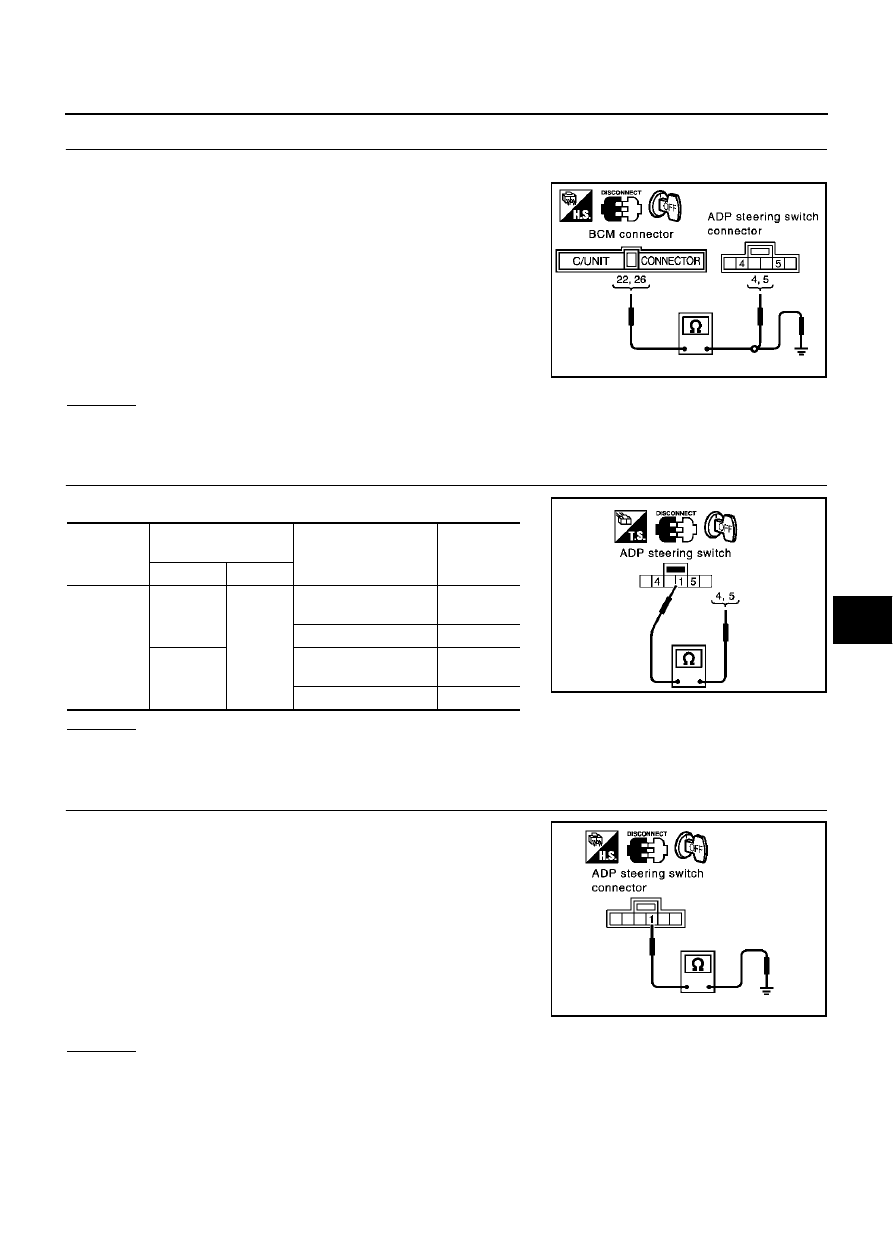
CHECK HARNESS CONTINUITY
1.
Disconnect BCM connector and ADP steering switch connector.
2.
Check continuity between BCM connector M4 terminals 22 (R),
26 (GY/R) and ADP steering switch connector M51 terminals 4
(GY/R), 5 (R).
3.
Check continuity between BCM connector M4 terminals 22 (R),
26 (GY/R) and ground.
OK or NG
OK
>> GO TO 4.
NG
>> Repair or replace harness between BCM and ADP steering switch.
4.
CHECK TELESCOPIC SWITCH
Check continuity between ADP steering switch.
OK or NG
OK
>> GO TO 5.
NG
>> Replace ADP steering switch.
5.
CHECK ADP STEERING SWITCH GROUND CIRCUIT
Check continuity between ADP steering switch connector M51 termi-
nal 1 (B) and ground.
OK or NG
OK
>> Check the condition of the harness and connector.
NG
>> Replace or replace harness between ADP steering switch and ground.
22 (R) – 5 (R)
: Continuity should exist.
26 (GY/R) – 4 (GY/R)
: Continuity should exist.
22 (R) – Ground
: Continuity should not exist.
26 (GY/R) – Ground
: Continuity should not exist.
PIIA3307E
Connector
Terminals
(Wire color)
Condition
Continuity
(+)
(–)
M51
4
1
Telescopic switch ON
(backward operation)
Yes
Telescopic switch OFF
No
5
Telescopic switch ON
(forward operation)
Yes
Telescopic switch OFF
No
PIIA4481E
1 (B) – Ground
:Continuity should exist.
PIIA3308E