Infiniti F50. Manual - part 770
AUTOMATIC DRIVE POSITIONER
SE-71
C
D
E
F
G
H
J
K
L
M
A
B
SE
3.
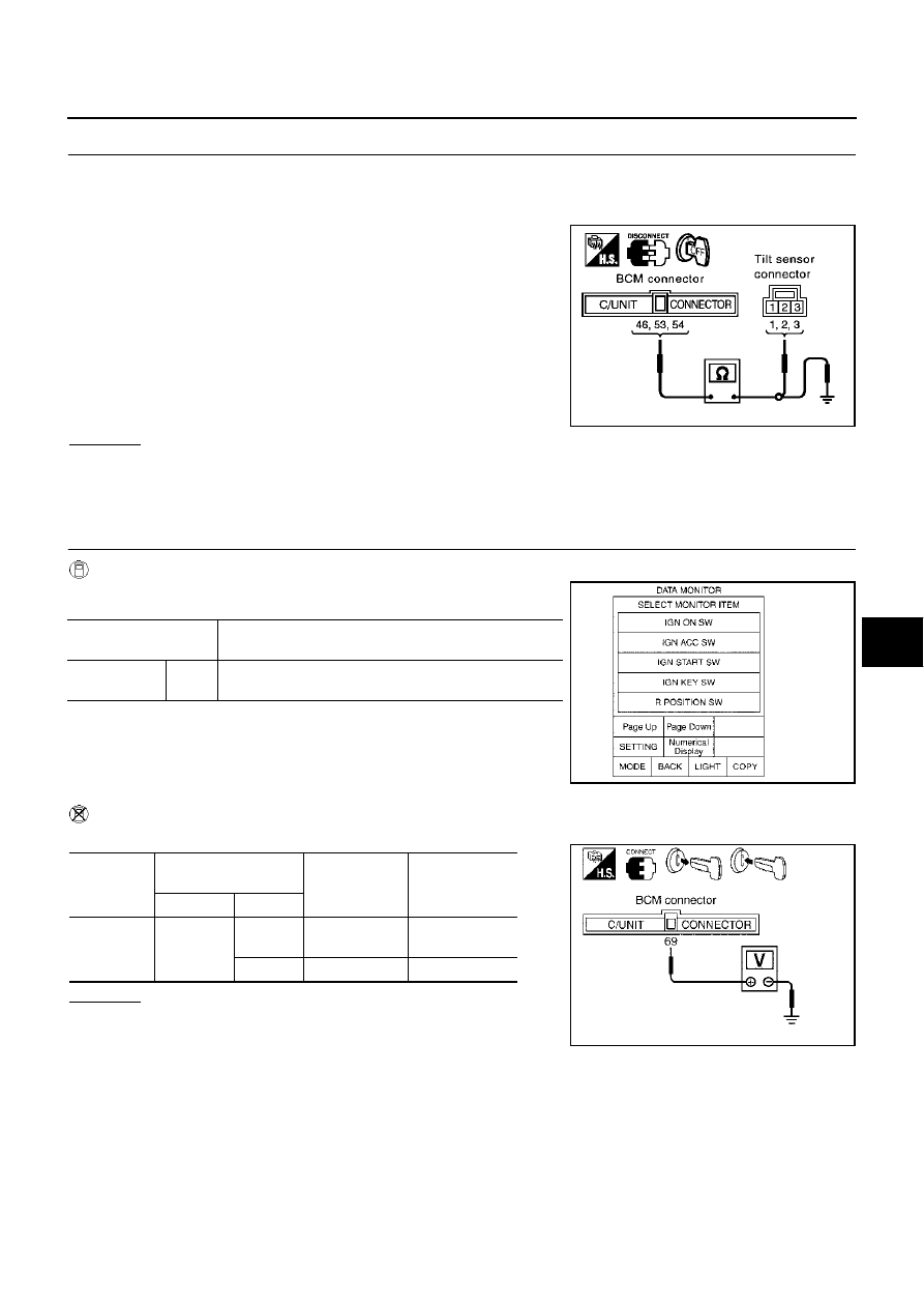
CHECK HARNESS
1.
Disconnect BCM connector and tilt sensor connector.
2.
Check continuity harness between BCM connector M4 terminals 46 (P/L), 53 (L/W), 54 (LG/B) and tilt
sensor connector M57 terminals 1 (LG/B), 2 (P/L), 3 (L/W).
3.
BCM connector M4 terminals 46 (P/L), 53 (L/W), 54 (LG/B) and
ground.
OK or NG
OK
>> Replace tilt sensor.
NG
>> Repair or replace harness between BCM and tilt sensor.
Key Switch and Key Lock Solenoid Circuit Inspection.
EIS0043N
1.
CHECK KEY SWITCH AND KEY LOCK SOLENOID
With CONSULT-II
With "IGN KEY SW" on the DATA MONITOR, Check ON/OFF opera-
tion.
Without CONSULT-II
Check voltage between BCM connector ground.
OK or NG
OK
>> System is OK.
NG
>> GO TO 2.
46 (P/L) – 2 (P/L)
: Continuity should exist.
53 (L/W) – 3 (L/W)
: Continuity should exist.
54 (LG/B) – 1 (LG/B)
: Continuity should exist.
46 (P/L) – Ground
: Continuity should not exist.
53 (L/W) – Ground
: Continuity should not exist.
54 (LG/B) – Ground
: Continuity should not exist.
PIIA3285E
Monitor item [OPERA-
TION or UNIT]
Contents
IGN KEY SW
"ON/
OFF"
Key inserted (ON)/key removed (OFF) status judged from
the key detection switch is displayed.
PIIA0298E
Connector
Terminals
(Wire color)
Condition
Voltage (V)
(Approx.)
(+)
(–)
M4
69 (PU/W)
ground
Remove the
key
0
ground
Insert the key
Battery voltage
PIIA0302E