Infiniti F50. Manual - part 762


  Index      Infiniti     Infiniti F50 - service repair manual 2006 year


Search            


Content   ..  760  761  762  763   ..


Infiniti F50. Manual - part 762


AUTOMATIC DRIVE POSITIONER

SE-39

C

D

E

F

G

H

J

K

L

M

A

B

SE

CONSULT-II Function 

EIS0043I

CONSULT–II executes the following functions by combining data received and transmits command transmis-
sion via the communication line from the BCM. IVMS communication inspection, work support by part, self-
diagnosis, data monitor, and active test display.

*: For setting seat and steering functions only.

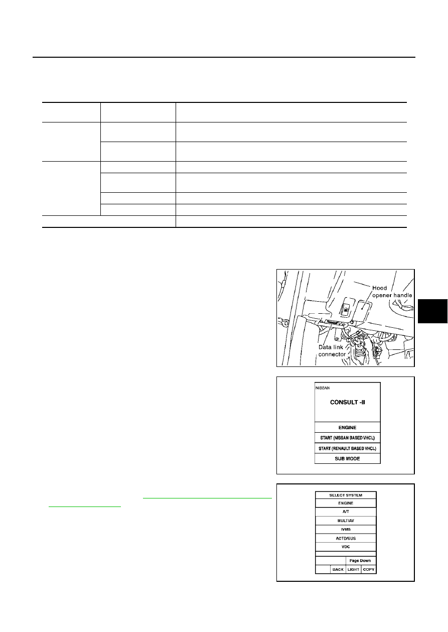
CONSULT-II BASIC OPERATION PROCEDURE

1.

Turn ignition switch “OFF”.

2.

Connect “CONSULT-II” and CONSULT-II CONVERTER to data
link connector.

3.

Turn ignition switch “ON”.

4.

Touch “START(NISSAN BASED VHCL)”.

5.

Touch “IVMS”on the “SELECT SYSTEM” screen.
If “IVMS” is not indicated, 

GI-38, "CONSULT-II Data Link Con-

nector (DLC) Circuit"

 .

IVMS diagnosis 

items

Inspection item, self-

diagnosis mode

Content

IVMS –
COMM CHECK

IVMS–
COMM DIAGNOSIS

Diagnoses a communication malfunction, inactive communication, and sleep 
malfunction in the communication line between the BCM and each LCU.

WAKE–
UP DIAGNOSIS

Diagnoses the wake-up signals output from each LCU.

AUTO DRIVE
POSITIONER

WORK SUPPORT*

Changes the setting for each function.

SELF–
DIG RESULTS

Perform the self-diagnosis.

DATA MONITOR

Displays the input data of the BCM and each LCU on real-time basis.

ACTIVE TEST

Gives a drive signal to a load to check the operation.

BCM PART NUMBER

Displays BCM part No.

PBIB1069E

MBIB0233E

PIIA0183E

SE-40

AUTOMATIC DRIVE POSITIONER

6.

Check the model specification, and touch either “WITH SUN-
ROOF” or “WITHOUT SUNROOF” on the “SELECT SYS
COND” screen.

7.

Touch “OK”. If the selection is wrong, touch “CANCEL”.

8.

Select the desired part to be diagnosed on the “SELECT TEST
ITEM” screen.

IVMS COMMUNICATION INSPECTION.

IVMS contains the IVMS communication diagnosis and wake-up diagnosis.

IVMS Communication Diagnosis

The function also stores the communication malfunction records and inactive communication records, and
displays the data on the CONSULT–II screen. (malfunction record diagnosis.)

NOTE:
Sleep is a power saving function when a vehicle is stationary (all BCM related electrical equipment: OFF,
and the timer: OFF).

*: Malfunction item record

Operation Procedure

1.

Touch “IVMS-COMM CHECK” on “SELECT TEST ITEM”.

2.

Touch “IVMS-COMM DIAGNOSIS” on the “SELECT DIAG ITEM” screen.

3.

Touch “START” on the “IVMS-COMM DIAGNOSIS” screen to start the diagnosis.

4.

After the diagnosis is completed, the malfunctioning system name is displayed.

5.

When the malfunctioning items are displayed, touch “PRINT” to keep the records.

6.

Touch “ERASE”.

7.

Carry out the communication inspection again to check that any malfunctioning item is displayed.

8.

Check the displayed items. 

Wake-up Diagnosis.

The wake-up diagnosis is carried out when the BCM detects the wake-up signal from each local control unit
(LCU). When the switch shown on the screen is operated as instructed, each local control unit (LCU) outputs
the wake-up signal. If the BCM cannot detect the wake-up signal, it is judged malfunctioning. The malfunction-
ing local control unit (LCU) is displayed on the screen.

Operation Procedure

1.

Touch “IVMS-COMM CHECK” on the “SELECT TEST ITEM” screen.

2.

Touch “WAKE-UP DIAGNOSIS” on the “SELECT DIAG ITEM” screen.

3.

Touch “START” on the “WAKE-UP DIAGNOSIS” screen to start the diagnosis.

PIIA0184E

Malfunction

CONSULT–II dis-

play item

Diagnosis content

Communication 
malfunction

COMM DATA

Communicating with each LCU is judged normal when communication is normally 
completed and when both transmitted data and received data are equal. In other 
cases, it is judged malfunctioning. If the communication is inactive, no diagnosis 
result is displayed.

Inactive communi-
cation

NO RESPONSE

Communicating with each LCU is judged normal when at least 1 communication is 
normally completed within 3 trials. In other cases, it is judged malfunctioning.

Sleep malfunction

SLEEP

Check that each LCU switches to sleep mode.

Communication 
malfunction*

PAST COMM
DATA

The records when communication signal, malfunctions were continuously detected 
while the communication was normal are displayed, or a malfunction was detected 
during the sleep control in the past are displayed.

Inactive communi-
cation*

PAST NO
RESPONSE

The records when inactive communications were continuously detected while the 
communication was normal are displayed.

AUTOMATIC DRIVE POSITIONER

SE-41

C

D

E

F

G

H

J

K

L

M

A

B

SE

4.

Touch “NEXT” to select the local control unit (LCU) to be diagnosed.

5.

Check that any malfunction is displayed. If necessary, touch “PRINT” to keep the record.

6.

Carry out the inspection of the malfunctioning item. 

Trouble Diagnosis Chart

NOTE:

For a specific local control unit (LCU), either “PAST COMM DATA” or “PAST NO RESPONSE” may be displayed instead of the
above results.The data record, causes this, so erase the records.
(The display only shows the incident records, they are not malfunctions caused during the diagnosis. One possible cause is that an
intermittent incident occurred.)

Follow the steps below to erase the memory. 
Carry out either disconnect BCM battery power supply or erase memory with CONSULT-II.

With the battery connected, if the local control unit (LCU) connector is disconnected and left for approximately 1 minute, the BCM
stores “NO RESPONSE” record.

COMMUNICATION SYSTEM A

1. 

CHECK BCM

Replace the BCM with a known-good one, and carry out the communication diagnosis. Refer to 

SE-40, "IVMS

Communication Diagnosis"

 .

OK or NG

OK

>> The harness and connector is checked, and it is normal, replace BCM

NG

>> GO TO 2.

Malfunctioning 

item

Display unit

CONSULT–II IVMS communication diagnosis 

content

Self-diagnosis 

trouble code 

No.

Malfunctioning system 

and reference

COMM DATA

One LCU is dis-
played.

POWER WINDOW  C/U–DR "COMMDATA"

24

Replace the displayed 
LCU.

DOOR MIRROR  C/U–RH "COMMDATA"

27

DOOR MIRROR  C/U–LH "COMMDATA"

37

POWER SEAT  C/U–DR "COMMDATA"

47

Multiple LCUs 
are displayed.

BCM
"COMMFAIL1"L1","COMMFAIL2"

Displays in 
order of 24 

27

37

47

and cycles 

from 24.

Communication system A: 
Refer to 

SE-41

 .

NO
RESPONSE

One LCU is dis-
played.

POWER WINDOW C/U–DR "NORESPONSE"

25

Communication system B: 
Refer to 

SE-42

DOOR MIRROR C/U–RH "NORESPONSE"

28

DOOR MIRROR C/U–LH "NORESPONSE"

38

POWER SEAT C/U–DR "NORESPONSE"

48

Multiple LCUs 
are displayed.

BCM/HARNESS

Displays in 
order of 
25

28

38

4

8 and cycles 
from 25.

Communication system 
C: Refer to 

SE-42

 .

SLEEP malfunc-
tion

One LCU is dis-
played.

POWER WINDOW C/U–DR "SLEEP"

No self-diagno-
sis function

Replace the displayed 
LCU.

DOOR MIRROR C/U–RH 
"SLEEP"

DOOR MIRROR C/U–LH 
"SLEEP"

POWER SEAT C/U–DR 
"SLEEP"

Multiple LCUs 
are displayed.

All the above control units are displayed.

No self-diagno-
sis function

Communication system A: 
Refer to 

SE-41

 .

SE-42

AUTOMATIC DRIVE POSITIONER

2. 

CHECK LCU

1.

Replace with the previously installed BCM.

2.

Replace the LCU with a known-good one, and carry out the communication diagnosis. Refer to 

SE-40,

"IVMS Communication Diagnosis"

 .

OK or NG

OK

>> The harness and connector is checked, and it is normal, replace LCU

NG

>> Repair or replace harness between the LCU and BCM.

COMMUNICATION SYSTEM B

1. 

CHECK HARNESS CONNECTOR

Check terminals (at the control unit and harness) on the malfunctioning LCU for disconnection, bend, loose
connection, and other malfunctions.

OK or NG

OK

>> GO TO 2.

NG

>> Repair the terminals and connectors.

2. 

CHECK LCU

Replace the malfunctioning LCU with a known-good one, and carry out the communication diagnosis. Refer to

SE-40, "IVMS Communication Diagnosis"

 .

OK or NG

OK

>> The harness and connector is checked, and it is normal, replace LCU

NG

>> Repair the harness between the indicated LCU and BCM.

COMMUNICATION SYSTEM C

1. 

CHECK HARNESS CONNECTOR

Check terminals (at the control unit and harness) on BCM and LCU for disconnection, bend, loose connection,
and other malfunctions.

OK or NG

OK

>> GO TO 2.

NG

>> Repair the terminals and connectors.

2. 

CHECK BCM

Replace the malfunctioning BCM with a known-good one, and carry out the communication diagnosis. Refer
to 

SE-40, "IVMS Communication Diagnosis"

 .

OK or NG

OK

>> The harness and connector is checked, and it is normal, replace BCM

NG

>> Repair the harness between the LCU and BCM control.

WORK SUPPORT
Display Item List

Refer to 

SE-36, "SETTING CHANGE FUNCTION"

 .


Content   ..  760  761  762  763   ..