Infiniti F50. Manual - part 745


  Index      Infiniti     Infiniti F50 - service repair manual 2006 year


Search            


Content   ..  743  744  745  746   ..


Infiniti F50. Manual - part 745


STARTING SYSTEM

SC-27

C

D

E

F

G

H

I

J

L

M

A

B

SC

DIAGNOSTIC PROCEDURE 2
Check “S” Connector Circuit

1. 

CHECK POWER SUPPLY FOR STARTER MOTOR “S” CONNECTOR

1.

Remove the fuel pump fuse.

2.

Crank or start the engine (where possible) until the fuel pressure is released.

3.

Turn the ignition switch OFF.

4.

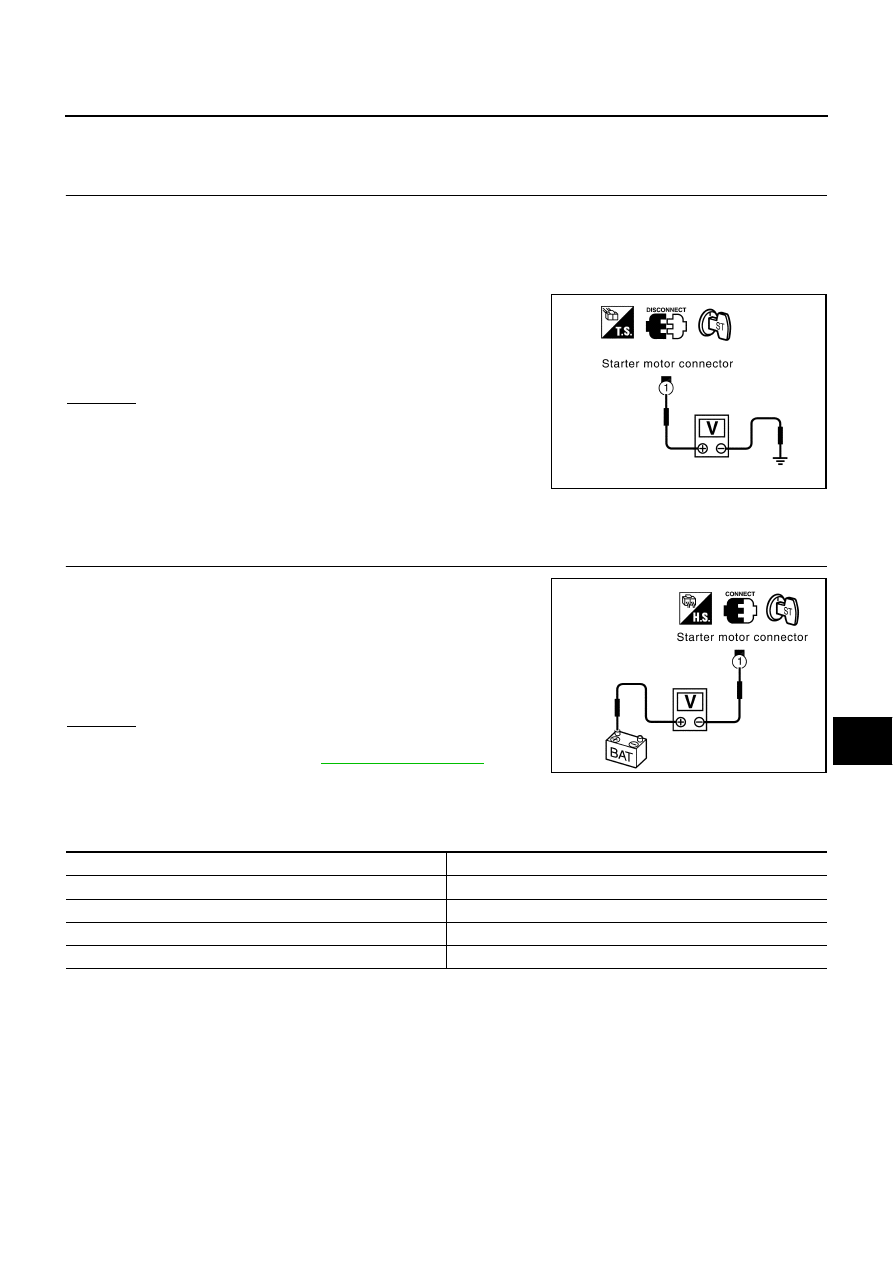
Disconnect starter motor connector.

5.

Check voltage between starter motor harness connector E312
terminal 1 (R) and ground using a digital circuit tester.

OK or NG

OK

>> GO TO 2.

NG

>> Check the following.

50A fusible link (letter G , located in fuse, fusible link
and relay box)

Park/neutral position relay

Harness for open or short

2. 

CHECK “S” TERMINAL CONNECTION (VOLTAGE DROP TEST)

1.

Connect starter motor connector.

2.

Check voltage between starter motor harness connector E312
terminal 1 (R) and battery positive terminal using a digital circuit
tester.

OK or NG

OK

>> Starter motor “S” connector circuit is OK. Further inspec-

tion necessary. Refer to 

SC-25, "WORK FLOW"

 .

NG

>> Check harness between the battery and the starter

motor “S” connector for poor continuity.

MINIMUM SPECIFICATION OF CRANKING VOLTAGE REFERENCING COOLANT TEMPERA-
TURE

When the ignition switch is in START position,

Battery voltage should exist.

SKIA0400E

When the ignition switch is in START position,

Voltage: Less than 1V

SKIA0401E

Engine coolant temperature

Voltage V

30

°

C to 

20

°

C (

22

°

F to 

4

°

F)

8.6

19

°

C to 

10

°

C (

2

°

F to 14

°

F)

9.1

9

°

C to 0

°

C (16

°

F to 32

°

F)

9.5

More than 1

°

C (More than 34

°

F)

9.9

SC-28

STARTING SYSTEM

Removal and Installation 

EKS000AD

REMOVAL 

1.

Remove negative battery terminal.

2.

Remove engine undercover.

3.

Disconnect S connector.

4.

Remove B terminal nut.

5.

Remove starter motor mounting bolt and nut.

6.

Remove engine mounting insulator (right side). Refer to 

EM-70,

"ENGINE ASSEMBLY"

  in “ENGINE MECHANICAL (EM)” sec-

tion.

7.

Remove starter motor from under the vehicle.

INSTALLATION

Install in the reverse order of removal.

PKIA0163E

B terminal nut:

 : 9.81 - 12.7 N·m (1.0 - 1.2 kg-m, 87 - 112 in-lb)

Starter motor mounting nut:

 : 41.2 - 52.0 N·m (4.2 - 5.3 kg-m, 31 - 38 ft-lb)

Starter motor mounting bolt:

 : 41.2 - 52.0 N·m (4.2 - 5.3 kg-m, 31 - 38 ft-lb)

STARTING SYSTEM

SC-29

C

D

E

F

G

H

I

J

L

M

A

B

SC

Disassembly and Assembly 

EKS000AE

Inspection After Disassembly 

EKS000AF

PINION/CLUTCH CHECK 

1.

Inspect pinion teeth.

Replace pinion if teeth are worn or damaged. (Also check condition of ring gear teeth.)

2.

Inspect reduction gear teeth.

Replace reduction gear if teeth are worn or damaged. (Also check condition of armature shaft gear
teeth.)

3.

Check to see if pinion locks in one direction and rotates smoothly in the opposite direction.

If it locks or rotates in both directions, or unusual resistance is evident, replace.

1.

Sleeve bearing

2.

Gear case

3.

Stopper clip

4.

Pinion stopper

5.

Pinion assembly

6.

Internal gear

7.

Plate

8.

Packing

9.

Adjusting plate

10. Magnetic switch assembly

11. Planetary gear

12. Ball

13. Packing

14. Yoke

15. Armature

16. Washer

17. Rear bearing

18. Brush holder assembly

19. Brush spring

20. Brush (-)

21. Rear cover

22. Cover

Through bolt:

 : 5.6 - 10.4 N·m (0.57 - 1.06 kg-m, 49.5 - 92.0 in-lb)

PKIA0162E

SC-30

SERVICE DATA AND SPECIFICATIONS (SDS)

SERVICE DATA AND SPECIFICATIONS (SDS)

PFP:00030

Battery

EKS0014C

Starter

EKS0014D

Alternator

EKS0014E

Type

80D23L

Capacity 

12 V - 52 AH

Cold cranking current (For reference value)

582 A

Type

M2T85171

MITSUBISHI make

Reduction gear type

System voltage

12 V

No-load

Terminal voltage

11 V

Current

Less than 145 A

Revolution

More than 3,300 rpm

Minimum diameter of commutator

31.4 mm (1.236 in)

Minimum length of brush

11.0 mm (0.433 in)

Brush spring tension

30.9 - 37.7 N (3.15 - 3.85 kg, 6.95 - 8.47 lb)

Clearance between bearing metal and armature shaft

Less than 0.2 mm (0.008 in)

Clearance between pinion front edge and pinion stopper

0.5 - 2.0 mm (0.020 - 0.079 in)

Type

A3TG0391

MITSUBISHI make

Nominal rating

12 V - 110 A

Ground polarity

Negative

Minimum revolution under no-load (When 13.5 V is applied)

Less than 1,000 rpm

Hot output current (When 13.5 V is applied)

More than 31 A / 1,300 rpm
More than 90 A / 2,500 rpm

More than 102 A / 5,000 rpm

Regulated output voltage

14.1 - 14.7 V

Minimum length of brush

More than 5.00 mm (0.197 in)

Brush spring pressure

4.8 - 6.1 N (490 - 610 g, 17.28 - 21.51 oz)

Slip ring minimum outer diameter

More than 22.1 mm (0.870 in)

Rotor (Field coil) resistance

1.7 - 2.1 


Content   ..  743  744  745  746   ..