Infiniti F50. Manual - part 732
PREPARATION
RSU-3
C
D
F
G
H
I
J
K
L
M
A
B
RSU
PREPARATION
PFP:00002
Special Service Tools
EES000U7
The actual shapes of Kent-Moore tools may differ from those of special service tools illustrated here.
Commercial Service Tools
EES000U8
Tool number
(Kent-Moore No.)
Tool name
Description
ST3127 S000
(See J25742-A)
Preload gauge
1. GC91030000
Torque wrench (J25765)
2. HT62940000 ( — )
Socket adapter (1/2
″
)
3. HT62900000 ( — )
Socket adapter (3/8
″
)
Measuring rotating torque of ball joint
NT124
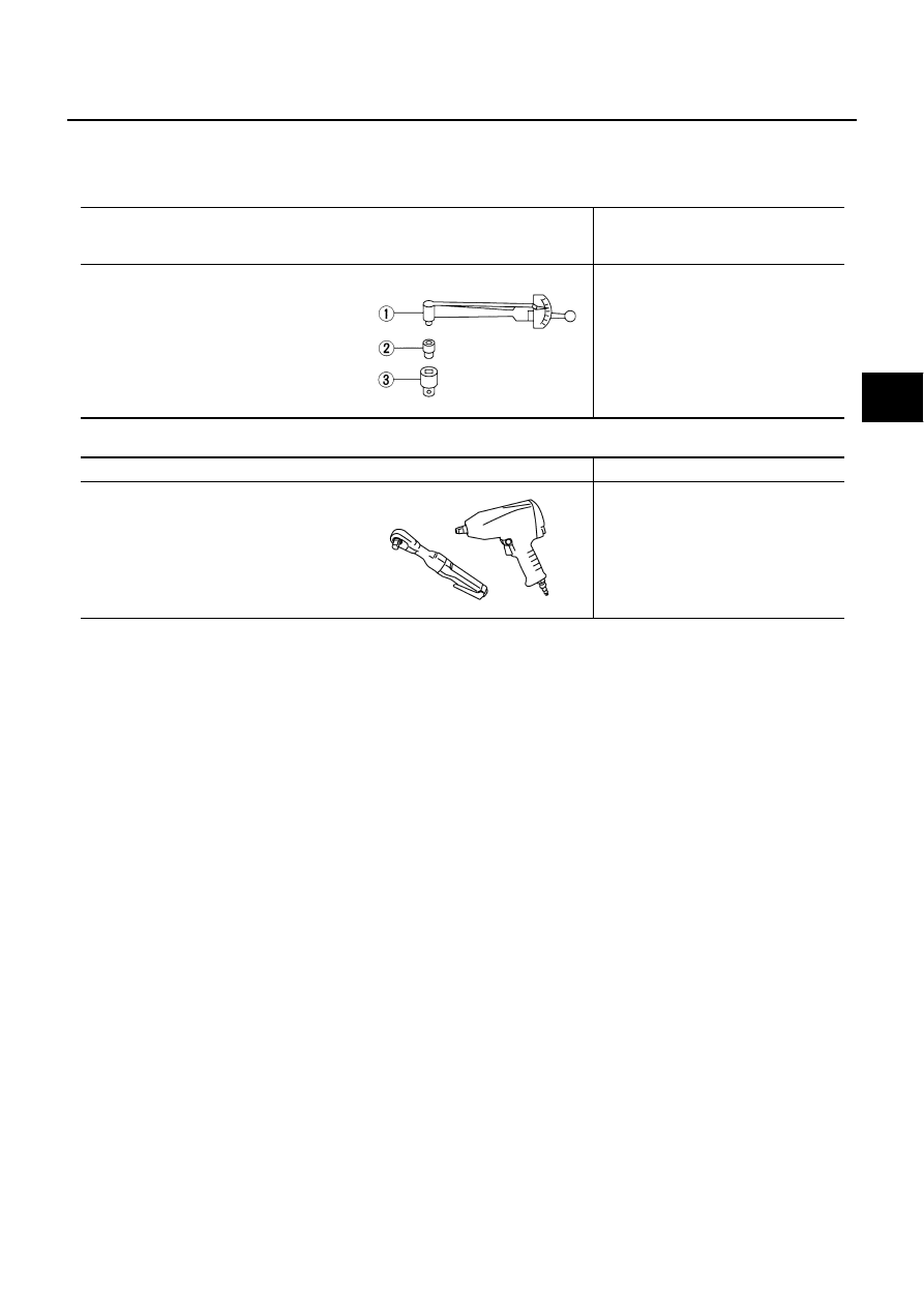
Tool name
Description
Power tool
●
Removing wheel nuts
●
Removing brake caliper
●
Removing stabilizer assembly
PBIC0190E