Infiniti F50. Manual - part 709
POWER STEERING OIL PUMP
PS-25
C
D
E
F
H
I
J
K
L
M
A
B
PS
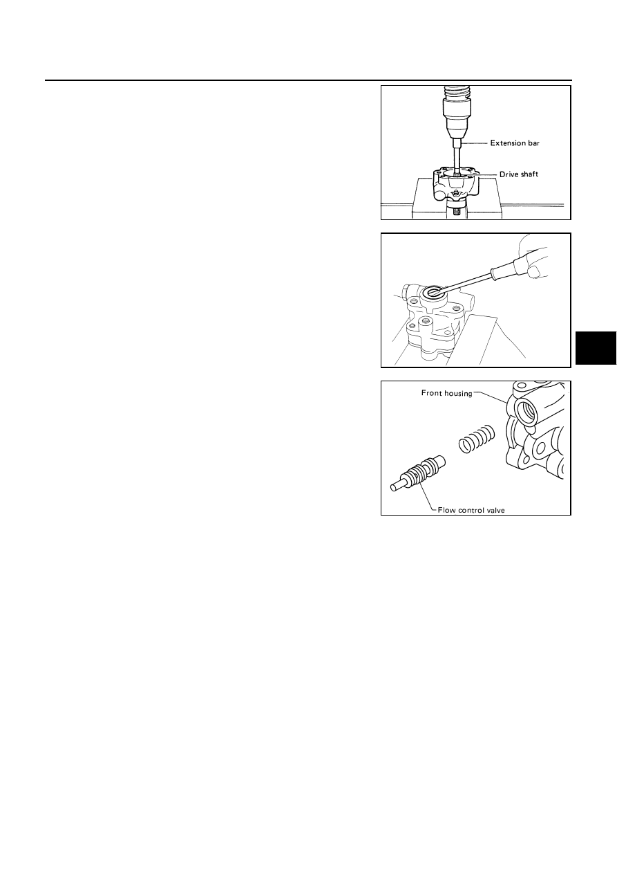
5.
Remove snap ring from drive shaft assembly and press out it.
CAUTION:
When removing snap ring, be careful not to damage drive
shaft assembly.
6.
Using a screwdriver, remove oil seal from housing.
7.
Remove O-ring from housing.
8.
Loosen lock nut and remove washer, joint then remove connec-
tor bolt, O-ring and pull out flow control valve and spring from
housing.
CAUTION:
Be careful not to drop and deform the flow control valve.
9.
Remove suction pipe from housing.
10. Remove O-ring from housing.
INSPECTION AFTER DISASSEMBLY
Housing and Rear cover Inspection
●
Check housing and the inside of rear cover for damage. If any damage is found, replace with new part for
rear cover and replace with new power steering pump assembly for housing.
Cartridge Assembly Inspection
●
Check cam ring, side plate, rotor and vane for damage. If any damage is found, replace cartridge assem-
bly with new one.
SST010B
SST034A
SST036A