Index Infiniti Infiniti F50 - service repair manual 2006 year
Search
Content .. 705 706 707 708 ..
Infiniti F50. Manual - part 707
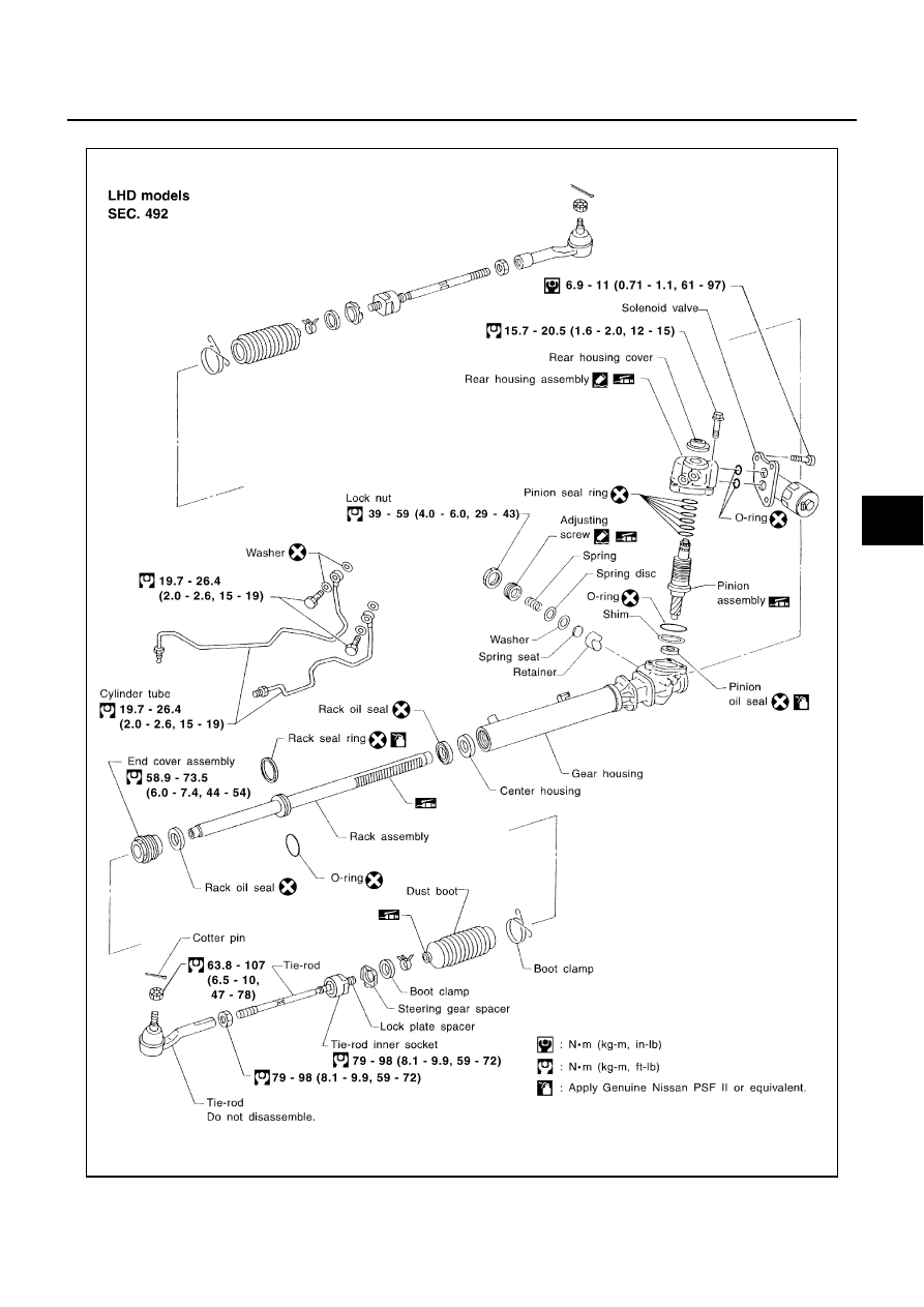
POWER STEERING GEAR AND LINKAGE
PS-17
C
D
E
F
H
I
J
K
L
M
A
B
PS
Component
EGS00074
SGIA0663E