Infiniti F50. Manual - part 673
OIL PUMP
LU-9
C
D
E
F
G
H
I
J
K
L
M
A
LU
OIL PUMP
PFP:15010
Removal and Installation
EBS0024Q
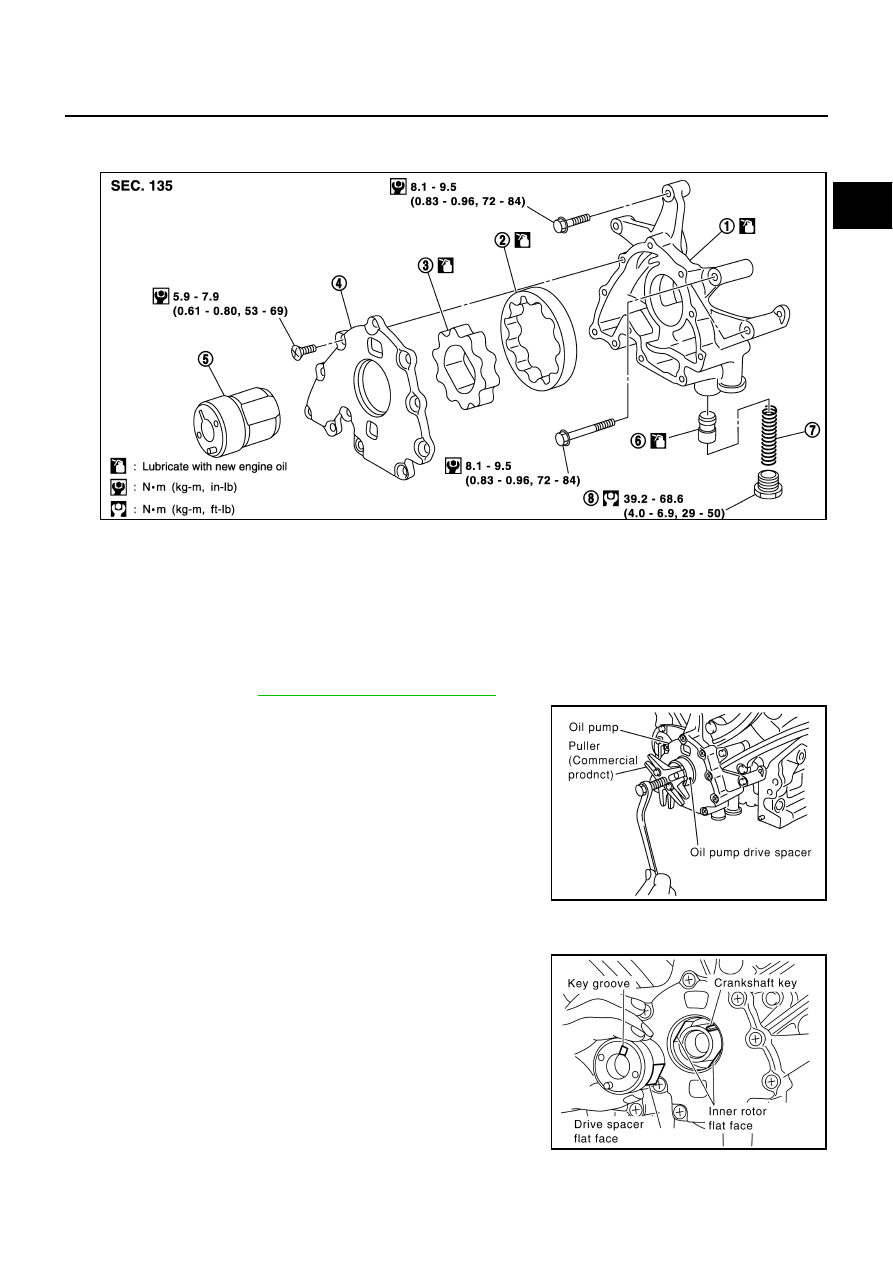
CAUTION:
Before installation, apply new engine oil to the parts as instructed in the figure.
REMOVAL
1.
Remove front cover.
Refer to Timing Chain,
EM-35, "Removal and Installation"
.
2.
Remove the oil pump drive spacer.
●
Set bolts in the two bolts holes [M6 x 1.0 mm (0.039 in)] on
the front surface. Using a small puller, remove the oil pump
drive spacer from the crankshaft.
NOTE:
The dimension between the centers of the two bolt holes is 33
mm (1.30 in).
In the figure, a commercial steering puller is used.
3.
Remove the oil pump.
INSTALLATION
1.
Install the oil pump.
2.
Install the oil pump drive spacer as follows.
a.
When inserting the oil pump drive spacer, align the crankshaft
key and the flat face of the inner rotor.
●
If they are not aligned, rotate the inner rotor by hand.
b.
Make sure that the each part is aligned. Using a tool such as a
plastic hammer, tap lightly until it reaches the end.
3.
Install in the reverse order of removal.
PBIC0994E
1.
Oil pump body
2.
Outer rotor
3.
Inner rotor
4.
Oil pump cover
5.
Oil pump drive spacer
6.
Regulator valve
7.
Regulator spring
8.
Regulator plug
PBIC0054E
PBIC0058E