Infiniti F50. Manual - part 630


  Index      Infiniti     Infiniti F50 - service repair manual 2006 year


Search            


Content   ..  628  629  630  631   ..


Infiniti F50. Manual - part 630


CAN SYSTEM (FOR ICC MODELS)

LAN-49

[CAN]

C

D

E

F

G

H

I

J

L

M

A

B

LAN

INSPECTION

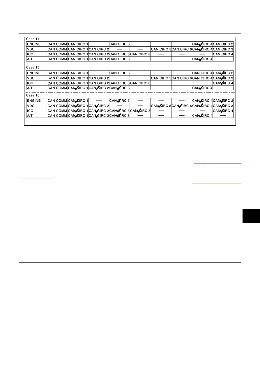
Proceed trouble diagnosis according to the check sheet results (example).
Case 1: Replace ECM.
Case 2: Replace VDC/TCS/ABS control unit.
Case 3: Replace ICC unit.
Case 4: Replace TCM.
Case 5: Check harness between VDC/TCS/ABS control unit and ICC sensor. Refer to 

LAN-49, "Circuit Check

VDC/TCS/ABS Control Unit and ICC Sensor"

 .

Case 6: Check harness between ICC sensor and ICC unit. Refer to 

LAN-50, "Circuit Check Between ICC sen-

sor and ICC unit"

 .

Case 7: Check harness between ICC unit and steering angle sensor. Refer to 

LAN-51, "Circuit Check

Between ICC unit and Steering Angle Sensor"

 .

Case 8: Check harness between steering angle sensor and combination meter. Refer to 

LAN-52, "Circuit

Check Between Steering Angle Sensor and Combination Meter"

 .

Case 9: Check ECM circuit. Refer to 

LAN-53, "ECM Circuit Check"

 .

Case 10: Check VDC/TCS/ABS control unit circuit. Refer to 

LAN-54, "VDC/TCS/ABS Control Unit Circuit

Check"

 .

Case 11: Check ICC sensor circuit. Refer to 

LAN-54, "ICC Sensor Circuit Check"

 .

Case 12: Check ICC unit circuit. Refer to 

LAN-55, "ICC Unit Circuit Check"

 .

Case 13: Check steering angle sensor circuit. Refer to 

LAN-55, "Steering Angle Sensor Circuit Check"

 .

Case 14: Check combination meter circuit. Refer to 

LAN-56, "Combination Meter Circuit Check"

 .

Case 15: Check TCM circuit. Refer to 

LAN-56, "TCM Circuit Check"

 .

Case 16: Check CAN communication circuit. Refer to 

LAN-57, "CAN Communication Circuit Check"

 .

Circuit Check VDC/TCS/ABS Control Unit and ICC Sensor

EKS003N8

1. 

CHECK CONNECTOR

1.

Turn ignition switch OFF.

2.

Check following terminals and connector for damage, bend and loose connection. (control unit-side, sen-
sor-side and harness-side)

VDC/TCS/ABS control unit.

ICC sensor.

OK or NG

OK

>> GO TO 2.

NG

>> Repair terminal or connector.

SKIA1249E

LAN-50

[CAN]

CAN SYSTEM (FOR ICC MODELS)

2. 

CHECK HARNESS FOR OPEN CIRCUIT

1.

Disconnect ECM connector, VDC/TCS/ABS control unit connector and ICC sensor connector.

2.

Check continuity between VDC/TCS/ABS control unit harness
connector E218 terminals 61 (LG/B), 63 (P/B) and ICC sensor
harness connector E52 terminals 3 (LG/B), 6 (P/B).

OK or NG

OK

>> Reconnect all connectors to perform “SELF-DIAG 

RESULTS” and “DATA MONITOR” for “ENGINE”, 
“VDC”, “ICC” and “A/T” displayed on CONSULT-II. Refer 
to the following:

EC-141, "DTC U1000, U1001 CAN COMMUNICA-
TION LINE"

 for “ENGINE”

BRC-58, "Inspection 16 CAN Communications Lines, VDC/TCS/ABS Control Unit and Steering
Angle Sensor System"

 for “VDC”

ACS-70, "DTC 20 CAN COMM CIRCUIT"

 for “ICC”

AT-99, "DTC U1000 CAN COMMUNICATION LINE"

 for “A/T”

NG

>> Repair harness.

Circuit Check Between ICC sensor and ICC unit

EKS003N9

1. 

CHECK CONNECTOR

1.

Turn ignition switch OFF.

2.

Check following terminals and connector for damage, bend and loose connection.(sensor-side, unit-side
and harness-side)

ICC sensor.

ICC unit.

Between ICC sensor and ICC unit.

OK or NG

OK

>> GO TO 2.

NG

>> Repair terminal or connector.

2. 

CHECK HARNESS FOR OPEN CIRCUIT

1.

Disconnect ICC sensor connector and harness connector E224.

2.

Check continuity between ICC sensor harness connector E52
terminals 3(LG/B), 6 (P/B) and harness connector E224 termi-
nals 6 (LG/B), 5 (P/B).

OK or NG

OK

>> GO TO 3.

NG

>> Repair harness.

61(LG/B) – 3(LG/B) 

: Continuity should exist.

63(P/B) – 6(P/B) 

: Continuity should exist.

SKIA1257E

3 (LG/B) – 6 (LG/B)

: Continuity should exist.

6 (P/B) – 5 (P/B)

: Continuity should exist.

SKIA3779E

CAN SYSTEM (FOR ICC MODELS)

LAN-51

[CAN]

C

D

E

F

G

H

I

J

L

M

A

B

LAN

3. 

CHECK HARNESS FOR OPEN CIRCUIT

1.

Disconnect ICC unit connector.

2.

Check continuity between harness connector B204 terminals 6
(LG/B), 5 (P/B) and ICC unit connector B243 terminals 14 (LG/
B), 5 (P/B).

OK or NG

OK

>> Reconnect all connectors to perform “SELF-DIAG 

RESULTS” and “DATA MONITOR” for “ENGINE”, 
“VDC”, “ICC” and “A/T” displayed on CONSULT-II. Refer 
to the following:

EC-141, "DTC U1000, U1001 CAN COMMUNICA-
TION LINE"

 for “ENGINE”

BRC-58, "Inspection 16 CAN Communications Lines, VDC/TCS/ABS Control Unit and Steering
Angle Sensor System"

 for “VDC”

ACS-70, "DTC 20 CAN COMM CIRCUIT"

 for “ICC”

AT-99, "DTC U1000 CAN COMMUNICATION LINE"

 for “A/T”

NG

>> Repair harness.

Circuit Check Between ICC unit and Steering Angle Sensor

EKS003M1

1. 

CHECK CONNECTOR

1.

Turn ignition switch OFF.

2.

Check following terminals and connector for damage, bend and loose connection.(unit-side, sensor-side
and harness-side)

ICC unit.

Steering angle sensor.

Between ICC unit and steering angle sensor.

OK or NG

OK

>> GO TO 2.

NG

>> Repair terminal or connector.

2. 

CHECK HARNESS FOR OPEN CIRCUIT

1.

Disconnect ICC unit connector and harness connector B263.

2.

Check continuity between ICC unit harness connector B243 ter-
minals 14 (LG/B), 5 (P/B) and harness connector B263 termi-
nals 9 (LG/B), 8 (P/B).

OK or NG

OK

>> GO TO 3.

NG

>> Repair harness.

6 (LG/B) – 14 (LG/B) 

: Continuity should exist.

5 (P/B) – 5 (P/B) 

: Continuity should exist.

SKIA3780E

14 (LG/B) – 9 (LG/B)

: Continuity should exist.

5 (P/B) – 8 (P/B)

: Continuity should exist.

SKIA1260E

LAN-52

[CAN]

CAN SYSTEM (FOR ICC MODELS)

3. 

CHECK HARNESS FOR OPEN CIRCUIT

1.

Disconnect harness connector B6.

2.

Check continuity between harness connector B63 terminals
9(LG/B), 8 (P/B) and harness connector B6 terminals 23(LG/B),
24 (P/B).

OK or NG

OK

>> GO TO 4.

NG

>> Repair harness.

4. 

CHECK HARNESS FOR OPEN CIRCUIT

1.

Disconnect steering angle sensor connector.

2.

Check continuity between harness connector M6 terminals
23(LG/B), 24 (P/B) and steering angle sensor harness connec-
tor M52 terminals 4 (LG/B), 5 (P/B).

OK or NG

OK

>> Reconnect all connectors to perform “SELF-DIAG 

RESULTS” and “DATA MONITOR” for “ENGINE”, 
“VDC”, “ICC” and “A/T” displayed on CONSULT-II. Refer 
to the following:

EC-141, "DTC U1000, U1001 CAN COMMUNICA-
TION LINE"

 for “ENGINE”

BRC-58, "Inspection 16 CAN Communications Lines, VDC/TCS/ABS Control Unit and Steering
Angle Sensor System"

 for “VDC”

ACS-70, "DTC 20 CAN COMM CIRCUIT"

 for “ICC”

AT-99, "DTC U1000 CAN COMMUNICATION LINE"

 for “A/T”

NG

>> Repair harness.

Circuit Check Between Steering Angle Sensor and Combination Meter

EKS003M2

1. 

CHECK CONNECTOR

1.

Turn ignition switch OFF.

2.

Check following terminals and connector for damage, bend and loose connection. (sensor-side, meter-
side and harness-side)

Steering angle sensor.

Combination meter.

OK or NG

OK

>> GO TO 2.

NG

>> Repair terminal or connector.

9 (LG/B) – 23 (LG/B) 

: Continuity should exist.

8 (P/B) – 24 (P/B) 

: Continuity should exist.

PKIA0276E

23 (LG/B) – 4 (LG/B) 

: Continuity should exist.

24 (P/B) – 5 (P/B) 

: Continuity should exist.

SKIA3775E


Content   ..  628  629  630  631   ..