Infiniti F50. Manual - part 601
REAR WINDOW DEFOGGER
GW-75
C
D
E
F
G
H
J
K
L
M
A
B
GW
6.
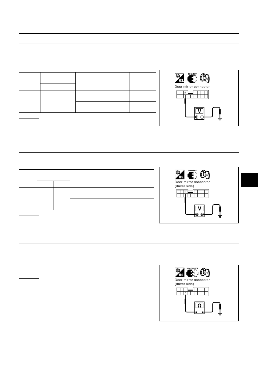
CHECK DOOR MIRROR DEFOGGER POWER SUPPLY CIRCUIT
1.
Connect door mirror defogger relay.
2.
Turn ignition switch ON.
3.
Check voltage between door mirror connector D2 (driver side) or D32 (passenger side) terminal 6 and
ground.
OK or NG
OK
>> INSPECTION END.
NG
>> Repair or replace harness between malfunction door
mirror and door mirror defogger relay.
Driver Side Door Mirror Defogger Circuit Check
EIS003T3
1.
CHECK DOOR MIRROR DEFOGGER POWER SUPPLY CIRCUIT
1.
Turn ignition switch ON.
2.
Check voltage between door mirror (driver side) connector and ground.
OK or NG
OK
>> GO TO 2.
NG
>> Repair or replace harness between door mirror defogger
relay and door mirror (driver side).
2.
CHECK DOOR MIRROR DEFOGGER GROUND HARNESS
1.
Turn ignition switch OFF.
2.
Disconnect door mirror (driver side) connector.
3.
Check continuity between driver side door mirror defogger connector D2 terminal 5 and ground.
OK or NG
OK
>> Check the following, if it is OK, replace door mirror
(driver side).
●
Check the condition of the harness and the connector.
●
Door mirror defogger firmament continuity check.
NG
>> Repair or replace harness between driver side door mir-
ror (driver side) and ground.
Connector
Terminals
(Wire color)
Condition
Voltage [V]
(Approx.)
(+)
(–)
D2
D32
6 (L/R)
Ground
Rear window defogger switch
ON
Battery
voltage
Rear window defogger switch
OFF
0
PIIA3521E
Con-
nector
Terminal
(Wire color)
Condition
Voltage [V]
(Approx.)
(+)
(–)
D2
6(L/R)
Ground
Rear window defogger
switch ON.
Battery voltage
Rear window defogger
switch OFF.
0
PIIA3523E
5 (B) – Ground
: Continuity should exist.
PIIA3524E