Infiniti F50. Manual - part 550
CYLINDER BLOCK
EM-87
C
D
E
F
G
H
I
J
K
L
M
A
EM
Use Undersize Bearing Usage Guide
●
Use undersize (US) bearing when oil clearance with standard size main bearing is not within specification.
●
When using undersize (US) bearing, measure inner diameter of bearing installed and grind journal until oil
clearance falls within specification.
Bearing undersize table
Unit: mm (in)
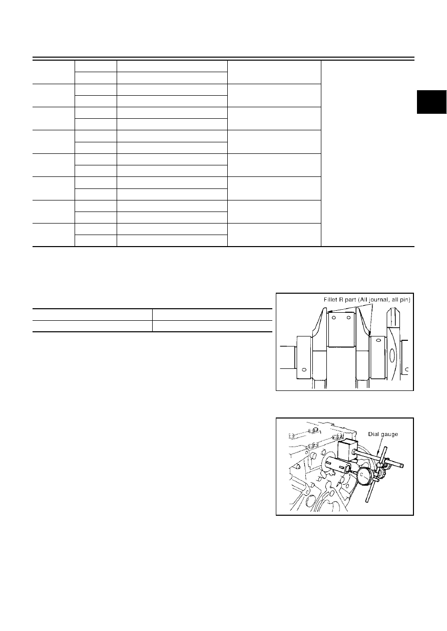
CAUTION:
Do not damage fillet R when grinding crankshaft journal in
order to use undersized bearing (All journals).
Inspection After Disassembly
EBS002MX
CRANKSHAFT END PLAY
●
Using a dial gauge, measure the clearance between the thrust
bearings and the crankshaft arm when the crankshaft is moved
fully forward or backward.
●
If the measured value exceeds the repair limit, replace the thrust
bearings, and measure again. If it still exceeds the repair limit,
replace the crankshaft also.
01
UPR
2.483 - 2.486 (0.0978 - 0.0979)
Black/Brown
Grade and color are different
for upper and lower bearings.
LWR
2.486 - 2.489 (0.0979 - 0.0980)
12
UPR
2.486 - 2.489 (0.0979 - 0.0980)
Brown/Green
LWR
2.489 - 2.492 (0.0980 - 0.0981)
23
UPR
2.489 - 2.492 (0.0980 - 0.0981)
Green/Yellow
LWR
2.492 - 2.495 (0.0981 - 0.0982)
34
UPR
2.492 - 2.495 (0.0981 - 0.0982)
Yellow/Blue
LWR
2.495 - 2.498 (0.0982 - 0.0983)
45
UPR
2.495 - 2.498 (0.0982 - 0.0983)
Blue/Pink
LWR
2.498 - 2.501 (0.0983 - 0.0985)
56
UPR
2.498 - 2.501 (0.0983 - 0.0985)
Pink/Purple
LWR
2.501 - 2.504 (0.0985 - 0.0986)
67
UPR
2.501 - 2.504 (0.0985 - 0.0986)
Purple/White
LWR
2.504 - 2.507 (0.0986 - 0.0987)
78
UPR
2.504 - 2.507 (0.0986 - 0.0987)
White/Red
LWR
2.507 - 2.510 (0.0987 - 0.0988)
Size
Thickness
US 0.25 (0.0098)
2.618 - 2.626 (0.1031 - 0.1034)
PBIC0111E
Standard
: 0.10 - 0.25 mm (0.0039 - 0.0098 in)
Limit
: 0.30 mm (0.0118 in)
PBIC0114E