Infiniti F50. Manual - part 546


  Index      Infiniti     Infiniti F50 - service repair manual 2006 year


Search            


Content   ..  544  545  546  547   ..


Infiniti F50. Manual - part 546


ENGINE ASSEMBLY

EM-71

C

D

E

F

G

H

I

J

K

L

M

A

EM

3.

Drain engine coolant from radiator drain plug. Refer to 

CO-9, "Changing Engine Coolant"

 .

4.

Remove the following parts:

Engine hood

Front tower bar 

Battery

Air duct (inlet)

Air duct and air cleaner case assembly

Drive belts (Refer to 

EM-13, "REMOVAL"

 .)

Power valve vacuum tank

Cooling fan and tubes

Radiator assembly and hoses (Refer to 

CO-12, "RADIATOR"

 .)

Water suction pipe

Engine room LH

5.

Disconnect engine room harness from the engine side and set it aside for easier work.

6.

Disconnect heater hoses, and install plugs to avoid leakage of engine coolant.

7.

Disconnect wire bonding exhaust manifold cover to vehicle.

8.

Disconnect vacuum hose between vehicle and engine and set it aside.

9.

Remove reservoir tank for cooling fan.

10. Remove A/C compressor from brackets, and install A/C compressor temporarily with ropes or equivalent

to avoid applying any pressures on piping or disturbing installation or removal of any vehicle parts. Refer
to 

ATC-144, "Compressor"

 .

Engine room RH
11. Disconnect fuel hose at the engine side connection.

For disconnection/connection of quick connector, refer to 

EM-31, "Removal and Installation"

 .

12. Disconnect engine room harness from the engine side and set it aside for easier work.

13. Disconnect wire bonding exhaust manifold cover to vehicle.

14. Disconnect vacuum hose between vehicle and engine and set it aside. 

15. Disconnect reservoir tank for power steering from engine and move it aside for easier work.

16. Move away relay case.
Vehicle underbody

17. Disconnect power steering oil pump from engine. Move it from its location and secure with a rope for eas-

ier work. Refer to 

PS-23, "POWER STEERING OIL PUMP"

 .

18. Remove pipe of cooler for automatic transmission.

19. Remove exhaust front tube.

20. Disconnect steering lower joint, and release steering shaft. Refer to 

PS-15, "POWER STEERING GEAR

AND LINKAGE"

 .

21. Disconnect propeller shaft. Refer to 

PR-3, "REAR PROPELLER SHAFT"

 .

After disconnection, plug the opening on transmission side.

Removal

22. Remove transmission assembly. Refer to 

AT-296, "TRANSMISSION ASSEMBLY"

 .

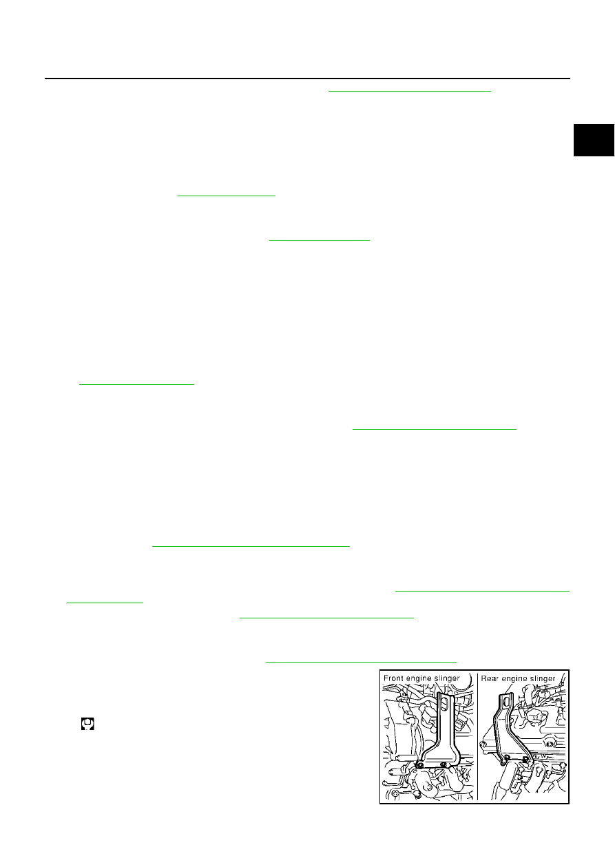
23. Install engine slingers into front of left bank cylinder head and

rear of right bank cylinder head.

24. Lift with hoist and secure the engine in position.

25. Remove engine mounting nuts on bottom surface.

26. Carefully lift up engine assembly, avoiding interference with

vehicle body, move it away and upward.

Slinger bolts:

: 30.4 - 36.3 N·m (3.1 - 3.7 kg-m, 23 - 26 ft-lb)

PBIC0082E

EM-72

ENGINE ASSEMBLY

27. With engine assembly lifted up, remove rear end of exhaust manifold to avoid contact with vehicle.

28. Remove engine assembly from vehicle.

CAUTION:

Before and during this lifting, always check if any har-
nesses are left connected.

Avoid damage to oil/grease smearing or spills onto
engine mount insulator.

INSTALLATION

Install in the reverse order of removal.

Where positioning pin is used, be sure to securely insert it into
the hole of mating part.

When installing front engine mount bracket to cylinder block, first
tighten two bolts on upper side. Then, tighten two bolts on lower
side. (The same applies to both right and left.)

INSPECTION AFTER INSTALLATION

Before starting engine, check the levels of engine coolant, lubrications, working oils.

Run engine to check for unusual noise and vibration.

Warm up engine thoroughly to make sure there is no leakage of engine coolant, lubricants, working oil,
fuel, and exhaust gas.

Bleed air from passages in pipes and tubes of applicable lines.

KBIA0372J

PBIC0083E

CYLINDER BLOCK

EM-73

C

D

E

F

G

H

I

J

K

L

M

A

EM

CYLINDER BLOCK

PFP:11010

Disassembly and Assembly

EBS001K6

1.

Knock sensor sub harness

2.

Knock sensor 

3.

Cylinder block

4.

Cover

5.

Main bearing

6.

Top ring

7.

Second ring

8.

Oil ring

9.

Crankshaft key

10.

Piston

11.

Connecting rod

12.

Snap ring

13.

Piston pin

14.

Connecting rod bearing

15.

Connecting rod bearing cap

16.

Block heater protector

17.

Connector cap

18.

Cylinder block heater (For Canada)

19.

Gasket

20.

Main bearing cap

21.

Thrust bearing

22.

Main bearing

23.

Rear plate

24.

Crankshaft

25.

Pilot convertor

26.

Drive plate

27.

Thrust bearing

28.

Side bolt

29.

Rain force plate

30.

Crankshaft position sensor (POS)

31.

O-ring

32.

Rear oil seal

33.

Rear oil seal retainer

SBIA0379E

EM-74

CYLINDER BLOCK

DISASSEMBLY

NOTE:
Explained here is how to disassemble with engine stand supporting transmission surface. When using differ-
ent type of engine stand, note with difference in steps and etc.

1.

Remove engine assembly. Refer to 

EM-70, "ENGINE ASSEMBLY"

 .

2.

Remove the parts that may restrict installation of engine to general-purpose engine stand.

NOTE:
The procedure is described assuming that you use a general-purpose engine stand holding the surface, to
which transmission is installed.

a.

Remove drive plate.

Holding crankshaft pulley mounting bolts, lock crankshaft to remove bolts fixing drive plate.

Loosen fixing bolts diagonally.

CAUTION:

Be careful not to damage drive plate. Especially, avoid deforming and damaging of signal plate
teeth (circumference position).

Place the drive plate with signal plate surface facing other than downward.

Keep magnetic materials away from signal plate.

b.

Remove engine rear plate.

3.

Lift the engine with hoist to install it onto the general-purpose engine stand.

CAUTION:

Use an engine stand that has a load capacity [240 kg (529 pound) or more] large enough for sup-
porting the engine weight. 

If the load capacity of the stand is not adequate, remove the following parts beforehand to reduce the
potential risk of overturning the stand.

Remove intake manifold upper and intake manifold lower. Refer to 

EM-17, "INTAKE MANIFOLD"

 . 

Remove exhaust manifold and three way catalyst. Refer to 

EM-22, "EXHAUST MANIFOLD AND

THREE WAY CATALYST"

 .

Remove fuel injector and fuel tube. Refer to 

EM-31, "FUEL INJECTOR AND FUEL TUBE"

 .

Remove starter motor. Refer to 

SC-28, "Removal and Installation"

 .

Remove ignition coil. Refer to 

EM-28, "IGNITION COIL"

 .

Remove rocker cover. Refer to 

EM-33, "ROCKER COVER"

 .

Other removable brackets.

NOTE:
The figure shows an example of general-purpose engine
stand that can hold mating surface of transmission with drive
plate and rear plate removed.

CAUTION:

Before removing the hanging chains, make sure the
engine stand is stable and there is no risk of overturning.

4.

Drain engine oil and engine coolant from inside of engine.

5.

Remove the following components and associated parts (The
parts listed in step 3 are not included here.)

Oil pan and oil strainer: Refer to 

EM-25, "OIL PAN AND OIL

STRAINER"

 .

Crankshaft pulley, front cover and timing chain: Refer to 

EM-35, "TIMING CHAIN"

 .

Camshaft: Refer to 

EM-46, "CAMSHAFT"

 .

Cylinder head: Refer to 

EM-61, "CYLINDER HEAD"

 .

6.

Remove knock sensor.

CAUTION:

Carefully handle the sensor, avoiding shocks.

PBIC0085E


Content   ..  544  545  546  547   ..