Infiniti F50. Manual - part 541


  Index      Infiniti     Infiniti F50 - service repair manual 2006 year


Search            


Content   ..  539  540  541  542   ..


Infiniti F50. Manual - part 541


CAMSHAFT

EM-51

C

D

E

F

G

H

I

J

K

L

M

A

EM

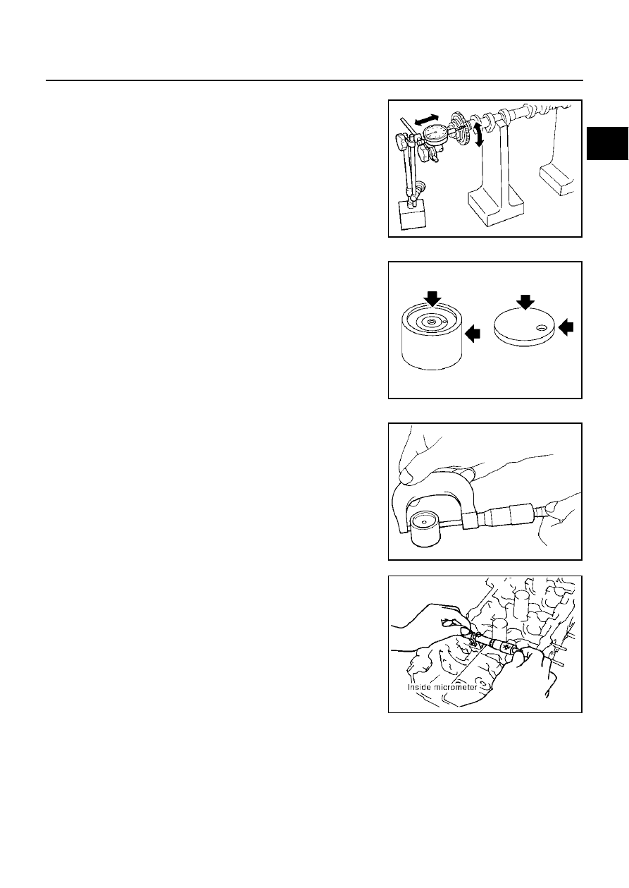
Camshaft Sprocket Runout

1.

Install camshaft in cylinder head.

2.

Install camshaft sprocket to camshaft.

3.

Measure camshaft sprocket runout.

4.

If it exceeds the specifications, replace camshaft sprocket.

Valve Lifter and Adjusting Shim

Check if surface of valve lifter and adjusting shim has any wear or
cracks.

Valve Lifter Clearance

Outer Diameter of Valve Lifter
Measure outer diameter of valve lifter.

Valve Lifter Hole Diameter
Using inside micrometer, measure diameter of valve lifter hole of cyl-
inder head.

Calculation of Valve Lifter Clearance
(Valve lifter clearance) = (hole diameter of valve lifter) – (outer diam-
eter of valve lifter)

When out of specified range, referring to each specification of outer and inner diameter, replace either or
both valve lifter and cylinder head.

Runout

: Less than 0.15 mm (0.0059 in)

PBIC0930E

PBIC0231E

Standard: 33.965 - 33.975 mm (1.3372 - 1.3376 in)

SEM961E

Standard:

34.000 - 34.016 mm (1.3386 - 1.3392 in)

Standard:

0.025 - 0.051 mm (0.0010 - 0.0020 in)

PBIC0043E

EM-52

CAMSHAFT

Valve Clearance

EBS002MQ

INSPECTION

Perform inspection as follows after removal, installation or replacement of camshaft or valve-related parts, or if
there is unusual engine conditions due to changes in valve clearance over time (starting, idling, and/or noise). 

1.

Warm up engine. Then, stop it.

2.

Remove engine cover and engine room covers (RH and LH) with power tool and air duct (inlet). Refer to

EM-11, "Removal and Installation"

 .

3.

Remove RH and LH rocker covers with power tool. Refer to 

EM-33, "Removal and Installation"

 .

4.

Turn crankshaft pulley in normal direction (clockwise when
viewed from FRONT) to align TDC identification notch (without
paint mark) with timing indicator.

5.

At this time, check that the both intake and exhaust cam noses
of No. 1 cylinder (top front on left bank) face outside.

If they do not face outside, turn crankshaft pulley once more.

6.

By referring to the figure, measure valve clearances at locations
marked X as shown in the table below (locations indicated with
black arrow in figure) with a thickness gauge.

NOTE:
Firing order 1-8-7-3-6-5-4-2

No.1 cylinder compression TDC

PBIC0044E

KBIA0400J

Measuring position (RH bank)

No.2 CYL

No.4 CYL

No.6 CYL

No. 8 CYL

No. 1 cylinder at TDC

 EXH


×

INT

×

×


Measuring position (LH bank)

No.1 CYL

No. 3 CYL

No. 5 CYL

No. 7 CYL

No. 1 cylinder at TDC

INT

×

×


EXH

×

×

PBIC0823E

CAMSHAFT

EM-53

C

D

E

F

G

H

I

J

K

L

M

A

EM

Use a fine thickness gauge. 

*Approximately 20

°

C (68

°

F)

CAUTION:

If inspection was carried out with cold engine, check that
values with fully warmed up engine are still within speci-
fications.

7.

Turn crankshaft pulley clockwise by 270

°

 from the position of No. 1 cylinder compression TDC to obtain

No. 3 cylinder compression TDC. 

8.

By referring to the figure, measure valve clearances at locations
marked X as shown in the table below (locations indicated with
white arrow in figure) 

No.3 cylinder compression TDC

9.

Turn crankshaft pulley clockwise by 90

°

 from the position of No.

3 cylinder compression TDC (clockwise by 360

°

 from the posi-

tion of No. 1 cylinder compression TDC) to measure intake and
exhaust valve clearances of No. 6 cylinder and exhaust valve
clearance of No.2 cylinder. 

10. If out of specifications, adjust as follows:

Valve clearance standard:

Hot

Intake

: 0.32 - 0.40 mm (0.013 - 0.016 in)

Exhaust

: 0.33 - 0.41 mm (0.013 - 0.016 in)

Cold*

Intake

: 0.26 - 0.34 mm (0.010 - 0.013 in)

Exhaust

: 0.29 - 0.37 mm (0.011 - 0.015 in)

PBIC0046E

Measuring position (RH bank)

No.2 CYL

No.4 CYL

No.6 CYL

No. 8 CYL

No. 3 cylinder at TDC

 EXH


×

INT


×

Measuring position (LH bank)

No.1 CYL

No. 3 CYL

No. 5 CYL

No. 7 CYL

No. 3 cylinder at TDC

INT

×

×


EXH

×

×

PBIC0823E

PBIC0824E

EM-54

CAMSHAFT

ADJUSTMENT

Adjust valve clearance while engine is cold.

1.

Turn crankshaft, to position cam lobe on camshaft of valve that
must be adjusted upward.

2.

Thoroughly wipe off engine oil around adjusting shim using a
rag.

3.

Using a extra-fine screwdriver, turn the round hole of the adjust-
ing shim in the direction of the arrow.

4.

Place Tool (A) around camshaft as shown in figure.

Before placing Tool (A), rotate cam lobe toward center of cyl-
inder head (See (1) in figure.) to simplify shim removal later.

CAUTION:

Be careful not to damage cam surface with Tool (A).

5.

Rotate Tool (A) (See (2) in figure.) so that valve lifter is pushed
down.

6.

Place Tool (B) between camshaft and the edge of the valve lifter
to retain valve lifter.

CAUTION:

Tool (B) must be placed as close to camshaft bracket as
possible.

Be careful not to damage cam surface with Tool (B).

7.

Remove Tool (A).

8.

Blow air into the hole to separate adjusting shim from valve lifter.

CAUTION:

When blowing, use goggles to protect your eye.

PBIC0047E

SBIA0408E

SEM870E

SEM871E


Content   ..  539  540  541  542   ..