Infiniti F50. Manual - part 505


  Index      Infiniti     Infiniti F50 - service repair manual 2006 year


Search            


Content   ..  503  504  505  506   ..


Infiniti F50. Manual - part 505


INJECTOR CIRCUIT

EC-661

C

D

E

F

G

H

I

J

K

L

M

A

EC

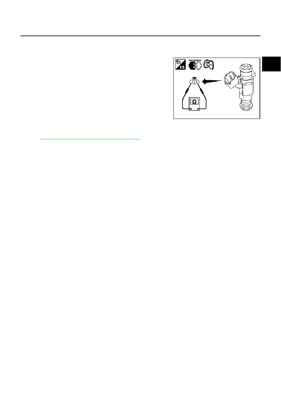
Component Inspection

EBS00MO5

INJECTOR

1.

Disconnect injector harness connector.

2.

Check resistance between terminals as shown in the figure.

Removal and Installation

EBS00MO6

INJECTOR

Refer to 

EM-31, "FUEL INJECTOR AND FUEL TUBE"

 .

Resistance: 13.5 - 17.5

 [at 20

°

C (68

°

F)]

PBIB1727E

EC-662

START SIGNAL

START SIGNAL

PFP:48750

CONSULT-II Reference Value in Data Monitor Mode

EBS00MO7

Specification data are reference values.

MONITOR ITEM

CONDITION

SPECIFICATION

START SIGNAL

Ignition switch: ON 

 START 

 ON

OFF 

 ON 

 OFF

START SIGNAL

EC-663

C

D

E

F

G

H

I

J

K

L

M

A

EC

Wiring Diagram

EBS00MO8

TBWM0042E

EC-664

START SIGNAL

Specification data are reference values and are measured between each terminal and ground.

CAUTION:

Do not use ECM ground terminals when measuring input/output voltage. Doing so may result in dam-
age to the ECM's transistor. Use a ground other than ECM terminals, such as the ground.

Diagnostic Procedure

EBS00MO9

1. 

INSPECTION START

Do you have CONSULT-II?

Yes or No

Yes

>> GO TO 2.

No

>> GO TO 3.

2. 

CHECK OVERALL FUNCTION

 With CONSULT-II

1.

Turn ignition switch “ON”.

2.

Check “START SIGNAL” in “DATA MONITOR” mode with CON-
SULT-II under the following conditions.

OK or NG

OK

>> INSPECTION END

NG

>> GO TO 4.

3. 

CHECK OVERALL FUNCTION

 Without CONSULT-II

Check voltage between ECM terminal 59 and ground under the fol-
lowing conditions.

OK or NG

OK

>> INSPECTION END

NG

>> GO TO 4.

4. 

CHECK STARTING SYSTEM

Turn ignition switch “OFF”, then turn it to “START”.
Does starter motor operate?

Yes or No

Yes

>> GO TO 5.

No

>> Refer to 

SC-22, "STARTING SYSTEM"

 .

TER-

MINAL 

NO.

WIRE 

COLOR

ITEM

CONDITION

DATA (DC Voltage)

59

SB

Start signal

[Ignition switch “ON”]

Approximately 0V

[Ignition switch “START”]

9 - 12V

Condition

START SIGNAL

Ignition switch “ON”

OFF

Ignition switch “START”

ON

PBIB0182E

Condition

Voltage

Ignition switch “START”

Battery voltage

Other positions

Approximately 0V

PBIB0677E


Content   ..  503  504  505  506   ..