Infiniti F50. Manual - part 477
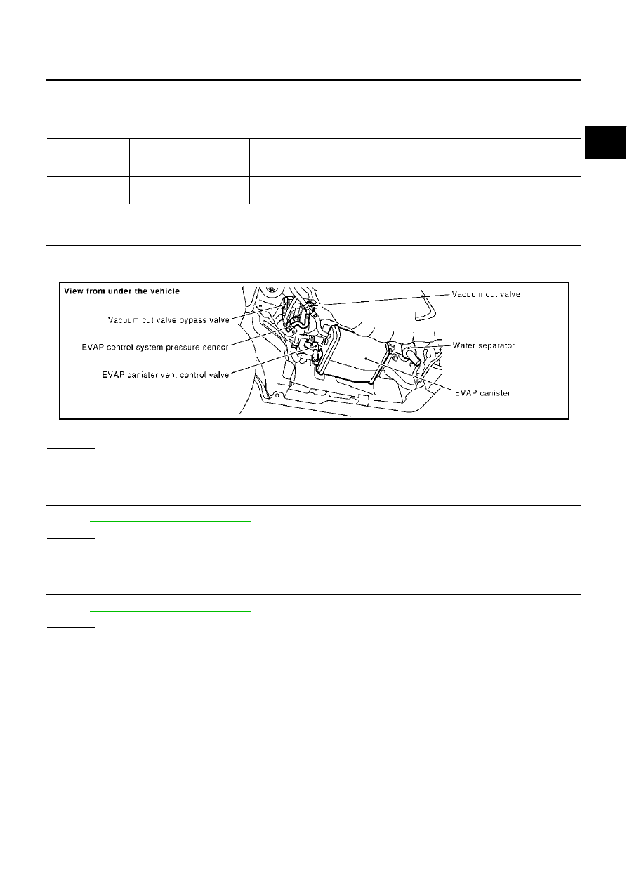
DTC P1446 EVAP CANISTER VENT CONTROL VALVE
EC-549
C
D
E
F
G
H
I
J
K
L
M
A
EC
Specification data are reference values and are measured between each terminal and ground.
CAUTION:
Do not use ECM ground terminals when measuring input/output voltage. Doing so may result in dam-
age to the ECM's transistor. Use a ground other than ECM terminals, such as the ground.
Diagnostic Procedure
ABS002QQ
1.
CHECK RUBBER TUBE
1.
Turn ignition switch “OFF”.
2.
Disconnect rubber tube connected to EVAP canister vent control valve.
3.
Check the rubber tube for clogging.
OK or NG
OK
>> GO TO 2.
NG
>> Clean rubber tube using an air blower.
2.
CHECK WATER SEPARATOR
Refer to
EC-338, "Component Inspection"
OK or NG
OK
>> GO TO 3.
NG
>> Clean or replace water separator.
3.
CHECK EVAP CANISTER VENT CONTROL VALVE
Refer to
EC-551, "Component Inspection"
OK or NG
OK
>> GO TO 4.
NG
>> Replace EVAP canister vent control valve.
TER-
MINAL
NO.
WIRE
COLOR
ITEM
CONDITION
DATA (DC Voltage)
158
L/Y
EVAP canister vent control
valve
[Ignition switch “ON”]
BATTERY VOLTAGE
(11 - 14V)
PBIB0026E