Infiniti F50. Manual - part 458


  Index      Infiniti     Infiniti F50 - service repair manual 2006 year


Search            


Content   ..  456  457  458  459   ..


Infiniti F50. Manual - part 458


DTC P1144, P1164 HO2S1

EC-473

C

D

E

F

G

H

I

J

K

L

M

A

EC

4. 

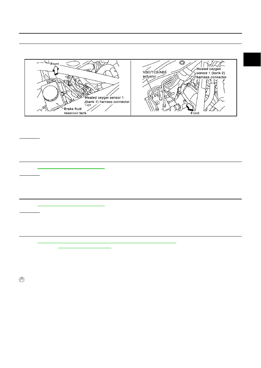
CHECK HO2S1 CONNECTOR FOR WATER

1.

Turn ignition switch “OFF”.

2.

Disconnect heated oxygen sensor 1 harness connector.

3.

Check connectors for water.

OK or NG

OK

>> GO TO 5.

NG

>> Repair or replace harness or connectors.

5. 

CHECK HEATED OXYGEN SENSOR 1 HEATER

Refer to 

EC-162, "Component Inspection"

 .

OK or NG

OK

>> GO TO 6.

NG

>> Replace malfunctioning heated oxygen sensor 1.

6. 

CHECK HEATED OXYGEN SENSOR 1

Refer to 

EC-473, "Component Inspection"

 .

OK or NG

OK

>> GO TO 7.

NG

>> Replace malfunctioning heated oxygen sensor 1.

7. 

CHECK INTERMITTENT INCIDENT

Refer to 

EC-132, "TROUBLE DIAGNOSIS FOR INTERMITTENT INCIDENT"

 .

For circuit, refer to 

EC-214, "Wiring Diagram"

 .

>> INSPECTION END

Component Inspection

EBS00MIU

HEATED OXYGEN SENSOR 1 

 With CONSULT-II

1.

Start engine and warm it up to normal operating temperature.

Water should not exist.

PBIB1250E

EC-474

DTC P1144, P1164 HO2S1

2.

Select “MANU TRIG” and adjust “TRIGGER POINT” to 100% in
“DATA MONITOR” mode with CONSULT-II. 

3.

Select “HO2S1 (B1)” and “HO2S1 MNTR (B1)”.

4.

Hold engine speed at 2,000 rpm under no load during the follow-
ing steps.

5.

Touch “RECORD” on CONSULT-II screen.

6.

Check the following.

“HO2S1 MNTR (B1)/(B2)” in “DATA MONITOR” mode
changes from “RICH” to “LEAN” to “RICH” more than 5 times
in 10 seconds.
5 times (cycles) are counted as shown at right.

“HO2S1 (B1)/(B2)” voltage goes above 0.6V at least once.

“HO2S1 (B1)/(B2)” voltage goes below 0.3V at least once.

“HO2S1 (B1)/(B2)” voltage never exceeds 1.0V.

CAUTION:

Discard any heated oxygen sensor which has been dropped from a height of more than 0.5 m (19.7
in) onto a hard surface such as a concrete floor; use a new one.

Before installing new oxygen sensor, clean exhaust system threads using Oxygen Sensor Thread
Cleaner tool J-43897-18 or J-43897-12 and approved anti-seize lubricant.

 Without CONSULT-II

1.

Start engine and warm it up to normal operating temperature.

2.

Set voltmeter probes between ECM terminal 114 [HO2S1 (B1) signal] or 115 [HO2S1 (B2) signal] and
engine ground.

3.

Check the following with engine speed held at 2,000 rpm con-
stant under no load.

The voltage fluctuates between 0 to 0.3V and 0.6 to 1.0V
more than 5 times within 10 seconds.

The maximum voltage is over 0.6V at least 1 time.

The minimum voltage is below 0.3V at least 1 time.

The voltage never exceeds 1.0V.

1 time: 0 - 0.3V 

 0.6 - 1.0V 

 0 - 0.3V

2 times: 0 - 0.3V 

 0.6 - 1.0V 

 0 - 0.3V 

 0.6 - 1.0V 

 0 -

0.3V

CAUTION:

Discard any heated oxygen sensor which has been dropped from a height of more than 0.5 m (19.7
in) onto a hard surface such as a concrete floor; use a new one.

SEF646Y

SEF647Y

SEF648Y

PBIB0063E

DTC P1144, P1164 HO2S1

EC-475

C

D

E

F

G

H

I

J

K

L

M

A

EC

Before installing new oxygen sensor, clean exhaust system threads using Oxygen Sensor Thread
Cleaner tool J-43897-18 or J-43897-12 and approved anti-seize lubricant.

Removal and Installation

EBS00MIV

HEATED OXYGEN SENSOR 1

Refer to 

EM-22, "EXHAUST MANIFOLD AND THREE WAY CATALYST"

 .

EC-476

DTC P1146, P1166 HO2S2

DTC P1146, P1166 HO2S2

PFP:226A0

Component Description

EBS00MIW

The heated oxygen sensor 2, after three way catalyst (manifold),
monitors the oxygen level in the exhaust gas on each bank.
Even if switching characteristics of the heated oxygen sensor 1 are
shifted, the air-fuel ratio is controlled to stoichiometric, by the signal
from the heated oxygen sensor 2.
This sensor is made of ceramic zirconia. The zirconia generates volt-
age from approximately 1V in richer conditions to 0V in leaner condi-
tions.
Under normal conditions the heated oxygen sensor 2 is not used for
engine control operation.

CONSULT-II Reference Value in Data Monitor Mode

EBS00MIX

Specification data are reference values.

On Board Diagnosis Logic

EBS00MIY

The heated oxygen sensor 2 has a much longer switching time
between rich and lean than the heated oxygen sensor 1. The oxygen
storage capacity of the three way catalyst (manifold) causes the
longer switching time. To judge the malfunctions of heated oxygen
sensor 2, ECM monitors whether the minimum voltage of sensor is
sufficiently low during the various driving condition such as fuel-cut.

SEF327R

MONITOR ITEM

CONDITION

SPECIFICATION

HO2S2 (B1)
HO2S2 (B2)

Warm-up condition

After keeping the engine speed 
between 3,500 and 4,000 rpm for 1 
minute and at idle for 1 minute under 
no load

Revving engine from idle up to 
3,000 rpm quickly.

0 - 0.3V 

←→

 Approx. 0.6 - 1.0V

HO2S2 MNTR (B1)
HO2S2 MNTR (B2)

Warm-up condition

After keeping the engine speed 
between 3,500 and 4,000 rpm for 1 
minute and at idle for 1 minute under 
no load

Revving engine from idle up to 
3,000 rpm quickly.

LEAN 

←→

 RICH

SEF972Z

DTC No.

Trouble diagnosis name

DTC detecting condition

Possible cause

P1146
1146
(Bank 1)

Heated oxygen sensor 2 
minimum voltage monitoring

The minimum voltage from the sensor is 
not reached to the specified voltage.

Harness or connectors
(The sensor circuit is open or shorted)

Heated oxygen sensor 2

Fuel pressure

Injectors

P1166
1166
(Bank 2)


Content   ..  456  457  458  459   ..