Index Infiniti Infiniti F50 - service repair manual 2006 year
Search
Content .. 434 435 436 437 ..
Infiniti F50. Manual - part 436
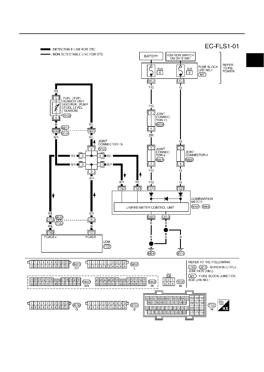
DTC P0460 FUEL LEVEL SENSOR
EC-385
C
D
E
F
G
H
I
J
K
L
M
A
EC
Wiring Diagram
EBS00MFM
TBWM0158E