Infiniti F50. Manual - part 412
DTC P0182, P0183 FTT SENSOR
EC-289
C
D
E
F
G
H
I
J
K
L
M
A
EC
Diagnostic Procedure
EBS00MD5
1.
CHECK FUEL TANK TEMPERATURE SENSOR POWER SUPPLY CIRCUIT
1.
Turn ignition switch “OFF”.
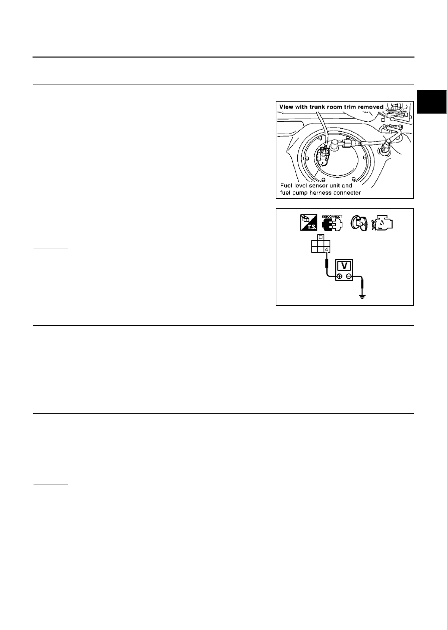
2.
Disconnect fuel level sensor unit and fuel pump harness con-
nector.
3.
Turn ignition switch “ON”.
4.
Check voltage between fuel level sensor unit and fuel pump ter-
minal 4 and ground with CONSULT-II or tester.
OK or NG
OK
>> GO TO 3.
NG
>> GO TO 2.
2.
DETECT MALFUNCTIONING PART
Check the following.
●
Harness connectors B211, M141
●
Harness connectors M135, F105
●
Harness for open or short between ECM and fuel level sensor unit and fuel pump
>> Repair harness or connector.
3.
CHECK FUEL TANK TEMPERATURE SENSOR GROUND CIRCUIT FOR OPEN AND SHORT
1.
Turn ignition switch “OFF”.
2.
Check harness continuity between fuel level sensor unit and fuel pump terminal 2 and body ground.
Refer to Wiring Diagram.
3.
Also check harness for short to power.
OK or NG
OK
>> GO TO 5.
NG
>> GO TO 4.
PBIB1249E
Voltage: Approximately 5V
PBIB0316E
Continuity should exist.