Infiniti F50. Manual - part 410


  Index      Infiniti     Infiniti F50 - service repair manual 2006 year


Search            


Content   ..  408  409  410  411   ..


Infiniti F50. Manual - part 410


DTC P0172, P0175 FUEL INJECTION SYSTEM FUNCTION

EC-281

C

D

E

F

G

H

I

J

K

L

M

A

EC

8. 

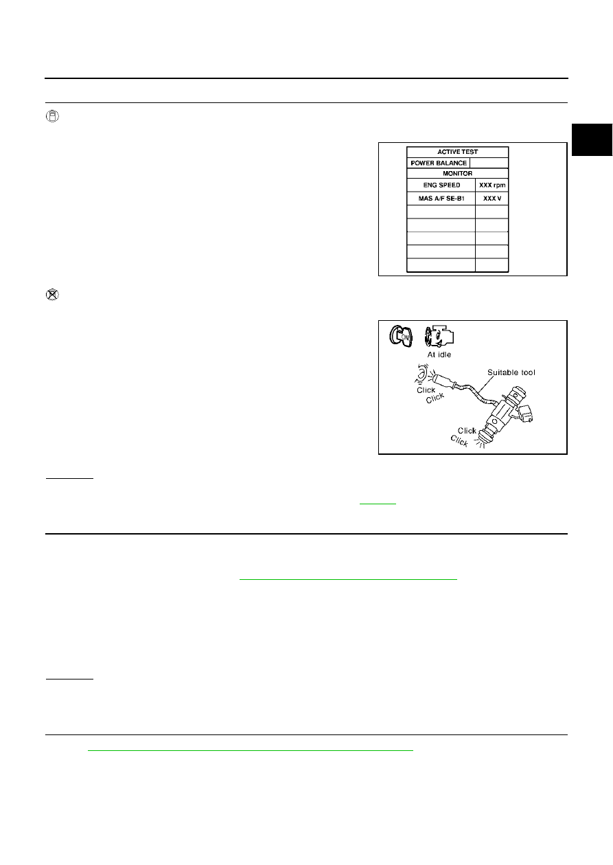
CHECK FUNCTION OF INJECTORS

 With CONSULT-II

1.

Start engine.

2.

Perform “POWER BALANCE” in “ACTIVE TEST” mode with
CONSULT-II.

3.

Make sure that each circuit produces a momentary engine
speed drop.

 Without CONSULT-II

1.

Start engine.

2.

Listen to each injector operating sound.

OK or NG

OK

>> GO TO 9.

NG

>> Perform trouble diagnosis for “INJECTOR CIRCUIT”, 

EC-653

 .

9. 

CHECK INJECTOR

1.

Turn ignition switch “OFF”.

2.

Confirm that the engine is cooled down and there are no fire hazards near the vehicle.

3.

Remove injector assembly. Refer to 

EM-31, "FUEL INJECTOR AND FUEL TUBE"

 .

Keep fuel hose and all injectors connected to injector gallery.

4.

Disconnect all injector harness connectors.

5.

Disconnect all ignition coil harness connectors.

6.

Prepare pans or saucers under each injectors.

7.

Crank engine for about 3 seconds.
Make sure fuel does not drip from injector.

OK or NG

OK (Does not drip.)>>GO TO 10.
NG (Drips.)>>Replace the injectors from which fuel is dripping. Always replace O-ring with new one.

10. 

CHECK INTERMITTENT INCIDENT

Refer to 

EC-132, "TROUBLE DIAGNOSIS FOR INTERMITTENT INCIDENT"

 .

>> INSPECTION END

PBIB0133E

Clicking noise should be heard.

PBIB1986E

EC-282

DTC P0181 FTT SENSOR

DTC P0181 FTT SENSOR

PFP:22630

Component Description

EBS00MCU

The fuel tank temperature sensor is used to detect the fuel tempera-
ture inside the fuel tank. The sensor modifies a voltage signal from
the ECM. The modified signal returns to the ECM as the fuel temper-
ature input. The sensor uses a thermistor which is sensitive to the
change in temperature. The electrical resistance of the thermistor
decreases as temperature increases.

<Reference data>

*: These data are reference values and are measured between ECM terminal 92
(Fuel tank temperature sensor) and ground.

CAUTION:

Do not use ECM ground terminals when measuring input/output
voltage. Doing so may result in damage to the ECM's transistor.
Use a ground other than ECM terminals, such as the ground.

On Board Diagnosis Logic

EBS00MCV

DTC Confirmation Procedure

EBS00MCW

NOTE:
If “DTC Confirmation Procedure” has been previously conducted, always turn ignition switch “OFF” and wait at
least 10 seconds before conducting the next test.

 WITH CONSULT-II

1.

Turn ignition switch “ON”.

2.

Select “DATA MONITOR” mode with CONSULT-II.

3.

Wait at least 10 seconds.
If 1st trip DTC is detected, go to 

EC-285, "Diagnostic Procedure"

.
If 1st trip DTC is not detected, go to following step.

4.

Check “COOLAN TEMP/S” value.
If “COOLAN TEMP/S” is less than 60

°

C (140

°

F), the result will

be OK.
If “COOLAN TEMP/S” is above 60

°

C (140

°

F), go to the following

step.

5.

Cool engine down until “COOLAN TEMP/S” is less than 60

°

C (140

°

F).

6.

Wait at least 10 seconds.

7.

If 1st trip DTC is detected, go to 

EC-285, "Diagnostic Procedure"

 .

PBIB1249E

Fluid temperature

°

C (

°

F)

Voltage*

V

Resistance

k

20 (68)

3.5

2.3 - 2.7

50 (122)

2.2

0.79 - 0.90

SEF012P

DTC No.

Trouble diagnosis name

DTC detecting condition

Possible cause

P0181
0181

Fuel tank temperature 
sensor circuit range/
performance

Rationally incorrect voltage from the sensor is 
sent to ECM, compared with the voltage sig-
nals from engine coolant temperature sensor 
and intake air temperature sensor.

Harness or connectors
(The sensor circuit is open or shorted)

Fuel tank temperature sensor

SEF174Y

DTC P0181 FTT SENSOR

EC-283

C

D

E

F

G

H

I

J

K

L

M

A

EC

 WITH GST

Follow the procedure “WITH CONSULT-II” above.

EC-284

DTC P0181 FTT SENSOR

Wiring Diagram

EBS00MCX

TBWM0153E


Content   ..  408  409  410  411   ..