Index Infiniti Infiniti F50 - service repair manual 2006 year
Search
Content .. 383 384 385 386 ..
Infiniti F50. Manual - part 385
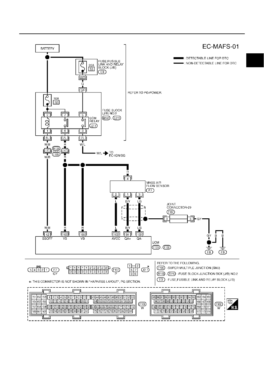
DTC P0102, P0103 MAF SENSOR
EC-181
C
D
E
F
G
H
I
J
K
L
M
A
EC
Wiring Diagram
EBS00LXP
TBWM0142E