Infiniti F50. Manual - part 374
POWER SUPPLY CIRCUIT FOR ECM
EC-137
C
D
E
F
G
H
I
J
K
L
M
A
EC
4.
CHECK ECM GROUND CIRCUIT FOR OPEN AND SHORT-I
1.
Turn ignition switch “OFF”.
2.
Disconnect ECM harness connector.
3.
Check harness continuity between ECM terminals 156, 159, 165, 168 and engine ground.
Refer to Wiring Diagram.
4.
Also check harness for short to power.
OK or NG
OK
>> GO TO 6.
NG
>> GO TO 5.
5.
DETECT MALFUNCTIONING PART
Check the following.
●
Joint connector-29
●
Harness for open or short between ECM and ground
>> Repair open circuit or short to power in harness or connectors.
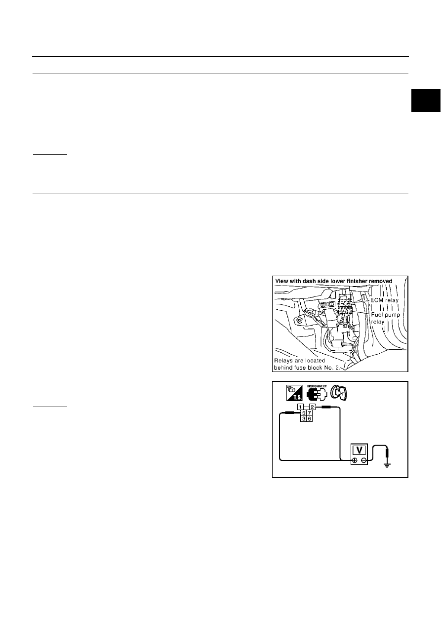
6.
CHECK POWER SUPPLY-II
1.
Disconnect ECM relay.
2.
Check voltage between ECM relay terminals 2, 5 and ground
with CONSULT-II or tester.
OK or NG
OK
>> GO TO 8.
NG
>> GO TO 7.
Continuity should exist.
PBIB0040E
PBIB0071E