Infiniti F50. Manual - part 373
POWER SUPPLY CIRCUIT FOR ECM
EC-133
C
D
E
F
G
H
I
J
K
L
M
A
EC
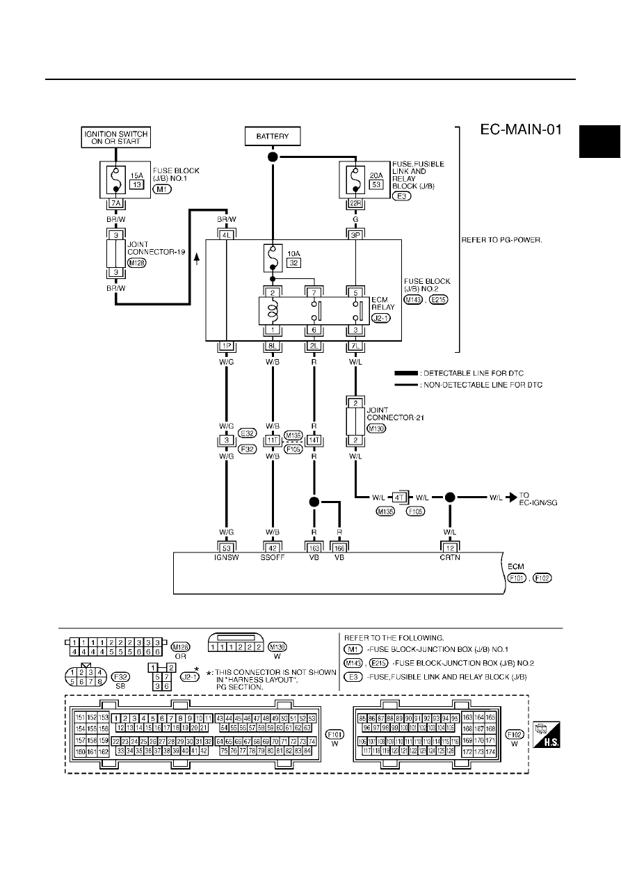
POWER SUPPLY CIRCUIT FOR ECM
PFP:24110
Wiring Diagram
EBS00LWG
TBWM0140E
|
|
|
POWER SUPPLY CIRCUIT FOR ECM EC-133 C D E F G H I J K L M A EC POWER SUPPLY CIRCUIT FOR ECM PFP:24110 Wiring Diagram EBS00LWG TBWM0140E |