Index Infiniti Infiniti F50 - service repair manual 2006 year
Search
Content .. 330 331 332 333 ..
Infiniti F50. Manual - part 332
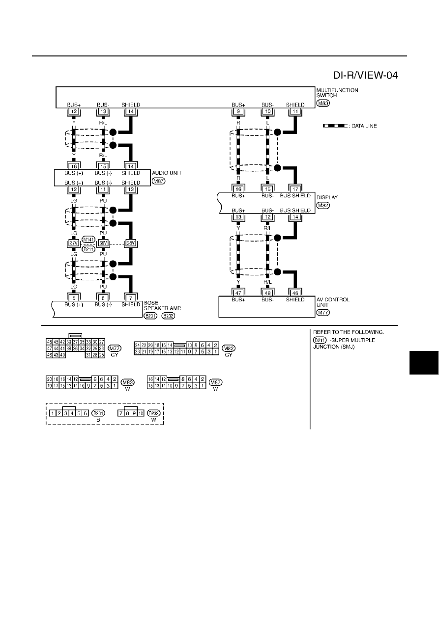
REAR VIEW MONITOR
DI-171
C
D
E
F
G
H
I
J
L
M
A
B
DI
WITHOUT NAVI
TKWM0390E