Infiniti F50. Manual - part 329
VEHICLE INFORMATION AND INTEGRATED SWITCH SYSTEM /WITH NAVIGA-
TION SYSTEM
DI-159
C
D
E
F
G
H
I
J
L
M
A
B
DI
Vehicle Condition Setting Is Not Possible
EKS006U2
1.
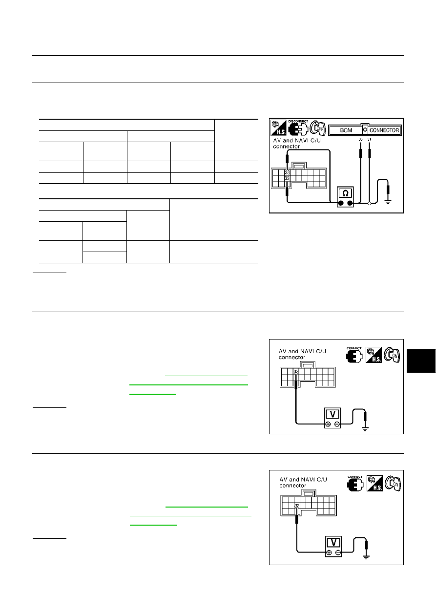
CHECK HARNESS
1.
Turn the ignition switch OFF.
2.
Disconnect connectors of combination meter, BCM, and AV and NAVI control unit.
3.
Check continuity AV and NAVI control unit and BCM.
4.
Check continuity between AV and NAVI control unit and ground.
OK or NG
OK
>> GO TO 2.
NG
>> Repair harness.
2.
CHECK COMMUNICATION SIGNAL (AV–ME)
1.
Connect connectors of combination meter, BCM, and AV and NAVI control unit.
2.
Turn the ignition switch ON.
3.
Check the signal between AV and NAVI control unit harness
connector B29 terminal 33 (LG) and ground with CONSULT-ll or
oscilloscope.
OK or NG
OK
>> GO TO 3.
NG
>> Replace AV and NAVI control unit
3.
CHECK COMMUNICATION SIGNAL (ME–AV)
1.
Turn ignition switch to ON and display “VEHICLE ELECTRONIC SYSTEMS” screen.
2.
Check the signal between AV and NAVI control unit harness
connector B29 terminal 32 (PU) and ground with CONSULT-ll or
oscilloscope.
OK or NG
OK
>> Replace AV and NAVI control unit.
NG
>> Replace BCM.
Terminals
Continuity
AV and NAVI control unit (+)
BCM (–)
Connector
Terminal
(Wire color)
Connector
Terminal
(Wire color)
B29
33 (LG)
M4
31 (LG)
YES
B29
32 (PU)
M4
30 (PU)
YES
Terminals
Continuity
AV and NAVI control unit (+)
(–)
Connector
Terminal
(Wire color)
B29
33 (LG)
Ground
NO
32 (PU)
SKIA3536E
33 (LG) – Ground
Reference Value for AV and NAVI
Control unit"
SKIA3534E
32 (PU) – Ground
Reference Value for AV and NAVI
Control unit"
SKIA3535E