Infiniti F50. Manual - part 306


  Index      Infiniti     Infiniti F50 - service repair manual 2006 year


Search            


Content   ..  304  305  306  307   ..


Infiniti F50. Manual - part 306


WARNING CHIME

DI-67

C

D

E

F

G

H

I

J

L

M

A

B

DI

Active Test Item (Key Warning Chime)

Active Test Item (Light Warning Chime)

Active Test Item (Seat Belt Warning Chime)
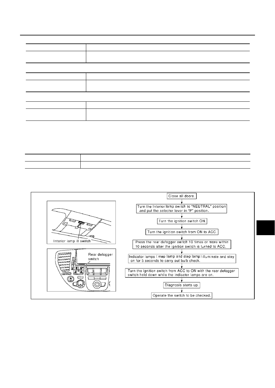
On Board Diagnosis

EKS001R0

ON BOARD DIAGNOSTIC RESULTS INDICATOR LAMP

Map lamps and step lamps (all seats) act as the indicators for the on board diagnosis.

DIAGNOSIS ITEM

SWITCH MONITOR

Perform the diagnosis on the switch system to each control unit.

How to Perform Switch Monitor

Test item

Malfunction detecting condition

CHIME

This test is able to check key warning chime operation. Key warning chime sounds for 2 sec-
onds after touching “ON” on CONSULT-ll screen.

Test item

Malfunction detecting condition

CHIME

This test is able to check light warning chime operation. Light warning chime sounds for 2 
seconds after touching “ON” on CONSULT-ll screen.

Test item

Malfunction detecting condition

CHIME

This test is able to check seat belt warning chime operation. Seat belt warning chime sounds 
for 2 seconds after touching “ON” on CONSULT-ll screen.

Diagnosis item

Description

Switch monitor

Monitoring conditions of switches connected to BCM.

SIIA0411E

DI-68

WARNING CHIME

Description

In this mode, when BCM detects the input signal from a switch in IVMS as shown below, the detection is
indicated by the map lamp and front step lamps with buzzer.

Switch Monitor Item

The status of the switch (except the ignition switch, interior lamp switch, and map lamp switch) as input to
each control unit can be monitored.

Cancel of Switch Monitor

Turn ignition switch OFF

Drive the vehicle at more than 7 km/h (4MPH).

Symptom Chart

EKS00114

SEL960V

BCM

Driver door switch

Lighting switch (1ST)

Seat belt buckle switch

Symptom

Possible cause and repair order

All warning chime does not activate.

Warning chime circuit check. Refer to 

DI-69, "Warning Chime 

Circuit Check"

If the above systems are work properly, replace the BCM.

Light warning chime does not activate (headlamp system is prop-
erly).

Lighting switch input signal check. Refer to 

DI-73, "Lighting 

Switch Input Signal Inspection"

Front door switch (driver side) check. Refer to 

DI-71, "Front 

Door Switch (Driver side) Inspection"

 .

If the above systems are work properly, replace the BCM.

Key warning chime does not activate.

Key switch insert signal check. Refer to 

DI-72, "Key Switch 

Insert Signal Inspection"

 .

Front door switch (driver side) check. Refer to 

DI-71, "Front 

Door Switch (Driver side) Inspection"

 .

If the above systems are work properly, replace the BCM.

Seat belt warning chime does not activate.

Check seat belt buckle switch input signal check. Refer to 

DI-

74, "Seat Belt Buckle Switch Inspection"

If the above systems are work properly, replace the BCM.

With the ignition switch turned OFF and the door closed (driver 
side), turning the lighting switch ON (1st) activates the chime.

Door switch (driver side) check. Refer to  

DI-71, "Front Door 

Switch (Driver side) Inspection"

 .

If the above systems are work properly, replace the BCM.

WARNING CHIME

DI-69

C

D

E

F

G

H

I

J

L

M

A

B

DI

Warning Chime Circuit Check

EKS00115

1. 

CHECK FUSES

Check 10A fuse [No. 6 located in fuse block (J/B) No. 1]
OK or NG

OK

>> GO TO 2.

NG

>> Replace the fuse.

2. 

CHECK POWER SUPPLY CIRCUIT

1.

Turn ignition switch OFF.

2.

Disconnect warning chime connector.

3.

Check voltage between warning chime harness connector M74
terminal 1 (Y/G) and ground.

OK or NG

OK

>> GO TO 3.

NG

>> Check harness for open or short between fuse and

warning chime.

3. 

CHECK WARNING CHIME SHORT CIRCUIT

1.

Disconnect BCM connector.

2.

Check continuity between warning chime harness connector
M74 terminal 3 (BR) and ground.

OK or NG

OK

>> GO TO 4.

NO

>> Repair harness or connector.

4. 

CHECK WARNING CHIME OPEN CIRCUIT

Check continuity between warning chime harness connector M74
terminal 3 (BR) and BCM harness connector M4 terminal 12 (BR).

OK or NG

OK

>> GO TO 5.

NG

>> Repair harness or connector.

Battery voltage should exist.

SKIA4135E

Continuity should not exist.

SKIA0525E

Continuity should exist.

SKIA0524E

DI-70

WARNING CHIME

5. 

CHECK WARNING CHIME OPERATION

1.

Connect warning chime connector.

2.

Ground warning chime harness connector M74 terminal 3 (BR).

OK or NG

OK

>> Replace BCM.

NG

>> Replace warning chime.

Warning chime should operate.

SKIA4136E


Content   ..  304  305  306  307   ..