Infiniti F50. Manual - part 289


  Index      Infiniti     Infiniti F50 - service repair manual 2006 year


Search            


Content   ..  287  288  289  290   ..


Infiniti F50. Manual - part 289


THERMOSTAT AND WATER CONTROL VALVE

CO-25

C

D

E

F

G

H

I

J

K

L

M

A

CO

7.

Disconnect fuel injector harness, and remove thermostat housing, water outlet pipe, rear water outlet and
heater pipe (between left and right banks).

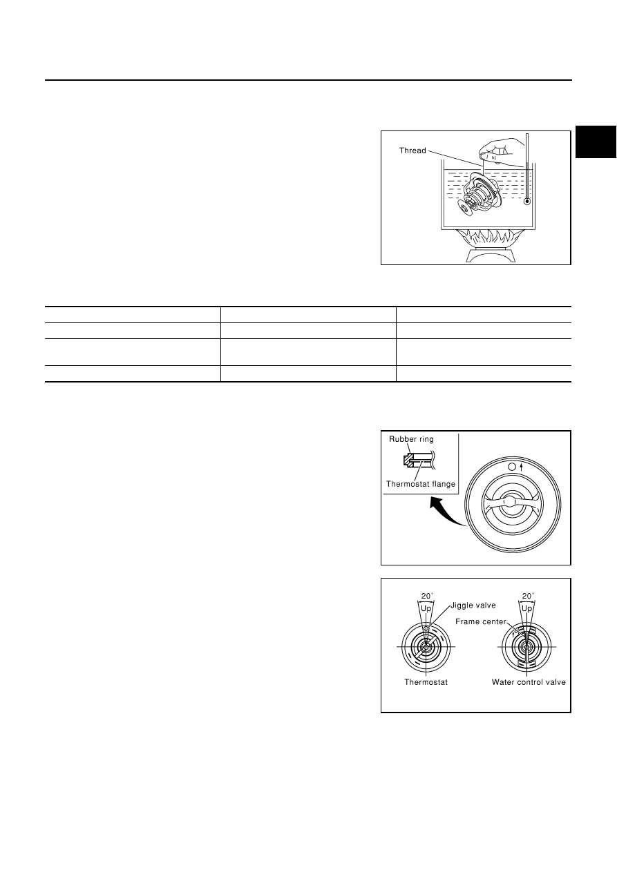
INSPECTION AFTER REMOVAL

Place a thread so that it is caught in the valves of the thermostat
and water control valve. Immerse fully in a container filled with
water. Heat while stirring. (The example in the figure shows the
thermostat.) 

The valve opening temperature is the temperature at which the
valve opens and falls from the thread. 

Continue heating. Check the full-open lift amount.

NOTE:
The full-open lift amount standard temperature for the water
control valve is the reference value.

 After checking the full-open lift amount, lower the water temper-
ature and check the valve closing temperature.

Standard values

INSTALLATION

Install in the reverse order of removal.
Installation of thermostat and water control valve

Install the thermostat and water control valve with the whole cir-
cumference of each flange part fit securely inside the rubber
ring. (The example in the figure shows the thermostat.) 

Install the thermostat with the jiggle-valve facing upwards. (The
position deviation may be within the range of 

±

10

°

)

Install the water control valve with the up-mark facing up and the
frame center part facing upwards. (The position deviation may
be within the range of 

±

10

°

)

Installation of water outlet pipe and heater pipe
First apply a neutral detergent to the O-rings, then quickly insert the insertion parts of the water outlet pipe and
heater pipe into the installation holes.

SLC252B

                        Thermostat

                   Water control valve

Valve opening temperature

               80 - 84

°

C (176 - 183

°

 F)     

            93.5 - 96.5

°

C (200 - 206

°

F)

Full-open lift amount

               More than 10 mm/ 95

°

C

                     (0.39 in/ 203 

°

F)

                More than 8 mm/ 108

°

C

                    (0.315 in/ 226 

°

 F)

Valve closing temperature

                77

°

C (171

°

F) or higher

                 90

°

C (194

°

 F) or higher

PBIC0157E

PBIC0158E

CO-26

SERVICE DATA AND SPECIFICATIONS (SDS)

SERVICE DATA AND SPECIFICATIONS (SDS)

PFP:00030

Standard and Limit

EBS003Q8

CAPACITY

THERMOSTAT

WATER CONTROL VALVE

RADIATOR

Unit: kPa (kg/cm

2

 , psi)

Tightening Torque

EBS002NI

Unit: N·m (kg-m, ft-lb)

Unit: N·m (kg-m, in-lb)*

Engine coolant capacity [With reservoir tank (MAX level)]

Approximately 9.8

 (10-3/8 US qt, 8-5/8 Imp qt)

Reservoir tank

0.8 

 (7/8 US qt, 3/4 lmp qt)

Cooling fan fluid capacity

777 m

 (26.3 US floz, 27.4 Imp floz)

Valve opening temperature

80 - 84

°

C (176 - 183

°

F)

Valve lift

More than 10 mm/95

°

C (0.39 in/203

°

F)

Valve closing temperature

77

°

C (171

°

F) or higher

Valve opening temperature

93.5 - 96.5

°

C (200 - 206

°

F)

Valve lift

More than 8 mm/108

°

C (0.315 in/226

°

F)

Valve closing temperature

90

°

C (194

°

F) or higher

Cap relief pressure

Standard

78 - 98 (0.8 - 1.0, 11 - 14)

Limit

59 (0.6, 9)

Leakage test pressure

157 (1.6, 23)

Cylinder block drain plug 

14.7 - 24.5 (1.5 - 2.5, 11 - 18)

Radiator mounting bracket
Radiator drain plug
Engine coolant temperature sensor
Cooling fan shroud
Reservoir tank bracket

3.8 - 4.5 (0.39 - 0.46, 34 - 39)*

0.78 - 1.56 (0.08 - 0.16, 7 - 14)*

4.9 - 9.8 (0.5 - 1.0, 44 - 86)*

3.8 - 4.5 (0.39 - 0.46, 34 - 39)*
3.8 - 4.5 (0.39 - 0.46, 34 - 39)*

Oil cooler securing nut (A/T model only)

8 - 12 (0.8 - 1.2, 69 - 104)*

Fan
Fan motor
Cooling fan fluid cooler
Fluid hose
Reservoir tank (Cooling fan pump)

7.8 - 11.8 (0.80 - 1.2, 70 - 104)*

3.9 - 4.9 (0.40 - 0.50, 35 - 43)*
3.0 - 3.9 (0.31 - 0.40, 27 - 34)*

14.7 - 17.7 (1.5 - 1.8, 11 - 13)

15.7 - 19.6 (1.6 - 1.9, 12 - 14)

Water pump pulley
Water pump

7.2 - 9.2 (0.73 - 0.94, 64 - 81)*

24.5 - 31.4 (2.5 - 3.2, 18 - 23)

Water inlet 
Thermostat housing
Rear water outlet
Water connector (Water control valve cover)
Water suction pipe
Heater pipe

16.7 - 22.6 (1.7 - 2.3, 13 - 16)
16.7 - 22.6 (1.7 - 2.3, 13 - 16)
16.7 - 22.6 (1.7 - 2.3, 13 - 16)
16.7 - 22.6 (1.7 - 2.3, 13 - 16)
16.7 - 22.6 (1.7 - 2.3, 13 - 16)

5.4 - 7.3 (0.55 - 0.75, 48 - 65)*

DI-1

DRIVER INFORMATION SYSTEM

K  ELECTRICAL

CONTENTS

C

D

E

F

G

H

I

J

L

M

SECTION 

A

B

DI

DRIVER INFORMATION SYSTEM

PRECAUTIONS .......................................................... 5

Precautions for Supplemental Restraint System 
(SRS) “AIR BAG” and “SEAT BELT PRE-TEN-
SIONER” .................................................................. 5
Wiring Diagrams and Trouble Diagnosis .................. 5

PREPARATION ........................................................... 6

Commercial Service Tools ........................................ 6

COMBINATION METERS ........................................... 7

System Description  .................................................. 7

UNIFIED CONTROL METER ................................ 7
HOW TO CHANGE THE DISPLAY FOR ODO/
TRIP METER  ........................................................ 7
POWER SUPPLY AND GROUND CIRCUIT  ........ 7
WATER TEMPERATURE GAUGE ........................ 8
TACHOMETER ..................................................... 8
FUEL GAUGE  ....................................................... 8
SPEEDOMETER ................................................... 8

CAN Communication ................................................ 9

SYSTEM DESCRIPTION  ...................................... 9
FOR VDC MODELS .............................................. 9
FOR ICC MODELS  ............................................. 10

Component Parts and Harness Connector Location 

....11

Combination Meter/Without ICC System  ............... 12

CHECK ................................................................ 12

Combination Meter/With ICC System  .................... 13

CHECK ................................................................ 13

Schematic .............................................................. 14
Wiring Diagram — METER — ................................ 15
Terminals and Reference Value for Combination 
Meter ...................................................................... 17
Meter/Gauges Operation, Odo/Trip Meter, A/T Indi-
cator and ICC System Display  ............................... 18

SELF-DIAGNOSIS FUNCTION  .......................... 18
HOW TO ALTERNATE DIAGNOSIS MODE  ....... 18

Work Flow  .............................................................. 19
Trouble Diagnoses  ................................................. 20

SYMPTOM CHART 1 (MALFUNCTION INDI-
CATED DIAGNOSIS MODE)  .............................. 20
SYMPTOM CHART 2 (NO MALFUNCTION INDI-
CATED IN DIAGNOSIS MODE) .......................... 20

Power Supply and Ground Circuit Check  ............... 21
Fluorescent Lamp Check ........................................ 22
Inspection/Engine Speed Signal ............................. 22
Inspection/Water Temperature Gauge .................... 23
Inspection/Vehicle Speed Signal  ............................ 23
Inspection/Fuel Level Sensor Unit .......................... 23

FUEL LEVEL SENSOR UNIT  ............................. 23
LOW-FUEL WARNING LAMP  ............................. 23

Fuel Gauge Pointer Fluctuates, Indicator Wrong 
Value, Or Varies ...................................................... 25
Fuel Gauge Does Not Move to Full-Position  .......... 25
Fuel Gauge Does Not Work  ................................... 25
Low-Fuel Warning Lamp Illuminate or Not Illuminate 

... 26

ICC System Display Does Not Illuminate  ............... 26
Electrical Components Inspection  .......................... 26

CHECK FUEL LEVEL SENSOR UNIT  ................ 26

Removal and Installation for Combination Meter .... 27

REMOVAL ........................................................... 27
INSTALLATION ................................................... 27

Disassembly and Assembly for Combination Meter ... 28

COMPASS ................................................................. 29

System Description ................................................. 29

DIRECTION DISPLAY ......................................... 29

Wiring Diagram – COMPAS –  ................................ 31
Removal and Installation of Compass  .................... 32

WARNING LAMPS .................................................... 33

System Description ................................................. 33

OUTLINE ............................................................. 33
AIR BAG WARNING LAMP ................................. 33
DOOR WARNING LAMP ..................................... 33
ACTIVE DAMPER INDICATOR LAMP (SPORT) ... 33
LOW OIL PRESSURE WARNING LAMP ............ 33
CHARGE WARNING LAMP  ................................ 33
LOW WASHER LEVEL WARNING LAMP  .......... 34
A/T OIL TEMPERATURE WARNING LAMP  ....... 34
LOW-FUEL LEVEL WARNING LAMP ................. 34
ABS WARNING LAMP  ........................................ 34
VDC OFF INDICATOR LAMP  ............................. 34
SLIP INDICATOR LAMP  ..................................... 34

DI-2

SEAT BELT WARNING LAMP ............................. 34
BRAKE WARNING LAMP  ................................... 35
MALFUNCTION INDICATOR LAMP  ................... 35
LOW TIRE PRESSURE WARNING LAMP  ......... 35
ASCD WARNING LAMP ...................................... 35
ICC SYSTEM WARNING LAMP .......................... 35
WARNING MESSAGE ON DISPLAY  .................. 35

Schematic ............................................................... 36
Wiring Diagram — WARN —  .................................. 37
Terminals and Reference Value for BCM ................ 46
Work Flow ............................................................... 46
Preliminary Inspection  ............................................ 46
CONSULT-II Function  ............................................. 47

DIAGNOSTIC ITEMS DESCRIPTION ................. 47
CONSULT-II BASIC OPERATION PROCEDURE 

... 47

DATA MONITOR .................................................. 48
ACTIVE TEST  ..................................................... 48

On Board Diagnosis  ............................................... 49

DIAGNOSIS ITEM  ............................................... 49
SWITCH MONITOR  ............................................ 49

Trouble Diagnosis for Door Warning Lamp ............. 50
Combination Meter Circuit Inspection ..................... 50
Front Door Switch Inspection  ................................. 51
Rear Door Switch Inspection  .................................. 52
Electrical Components Inspection  .......................... 53

OIL PRESSURE SWITCH ................................... 53
DIODE CHECK .................................................... 53

A/T INDICATOR  ........................................................ 54

Wiring Diagram — AT/IND —  ................................. 54
A/T Indicator Does Not Illuminate  ........................... 55

WARNING CHIME ..................................................... 56

System Description ................................................. 56

FUNCTION .......................................................... 56
IGNITION KEY WARNING CHIME ...................... 56
LIGHT WARNING CHIME  ................................... 56
SEAT BELT WARNING CHIME  ........................... 57

Component Parts and Harness Connector Location ... 57
Major Component Parts and Function  .................... 57
Schematic ............................................................... 58
Wiring Diagram — CHIME —  ................................. 59
Terminals and Reference Value Chart for BCM ...... 63
Work Flow ............................................................... 63
Preliminary Inspection  ............................................ 64

INSPECTION FOR POWER SUPPLY AND 
GROUND CIRCUIT  ............................................. 64

CONSULT-II Function  ............................................. 65

DIAGNOSTIC ITEMS DESCRIPTION ................. 65
CONSULT-II BASIC OPERATION PROCEDURE 

... 65

DATA MONITOR .................................................. 66
ACTIVE TEST  ..................................................... 66

On Board Diagnosis  ............................................... 67

DIAGNOSIS ITEM  ............................................... 67
SWITCH MONITOR  ............................................ 67

Symptom Chart ....................................................... 68
Warning Chime Circuit Check ................................. 69
Front Door Switch (Driver side) Inspection  ............. 71
Key Switch Insert Signal Inspection  ....................... 72

Lighting Switch Input Signal Inspection  ..................73
Seat Belt Buckle Switch Inspection .........................74
Removal and Installation of Warning Chime  ...........75

REMOVAL ............................................................75
INSTALLATION ....................................................75

VEHICLE INFORMATION AND INTEGRATED 
SWITCH SYSTEM /WITHOUT NAVIGATION SYS-
TEM ...........................................................................76

System Description  .................................................76

INTEGRATED SWITCH SYSTEM  .......................76
PRECAUTION OF LCD MONITOR  .....................76
POWER SUPPLY AND GROUND  .......................76
AV COMMUNICATION LINE  ...............................76
VEHICLE INFORMATION SYSTEM ....................77
SETTING OF VEHICLE STATUS  ........................79
WARNING INDICATIONS ....................................82

Precautions for AV Control Unit Replacement  ........84
Component Parts and Harness Connector and Har-
ness Connector Location  ........................................84
Schematic ...............................................................85
Wiring Diagram — INF/D — ....................................86
Schematic ...............................................................94
Wiring Diagram — COMM — ..................................95
Terminals and Reference Value for AV Control Unit .101
Terminals and Reference Value for Display  ..........104
Terminals and Reference Value for Multifunction 
Switch ...................................................................106
On Board Self-Diagnosis Function (without CON-
SULT-II) .................................................................108

DESCRIPTION ..................................................108
DIAGNOSIS ITEM  .............................................108

Self-Diagnosis Mode .............................................109

OPERATION PROCEDURE  ..............................109
SELF-DIAGNOSIS RESULT .............................. 111

Confirmation/Adjustment Mode ............................. 113

OPERATION PROCEDURE  .............................. 113
DISPLAY DIAGNOSIS  ....................................... 114
VEHICLE SIGNALS  ........................................... 115
SPEAKER TEST ................................................ 115
AUTO CLIMATE CONTROL  .............................. 115
REARVIEW CAMERA  ....................................... 115

CONSULT-II Function  ........................................... 116

CONSULT-II BASIC OPERATION PROCEDURE 

. 116

SELF-DIAG RESULTS ....................................... 117
DATA MONITOR  ................................................ 117
VERSION ........................................................... 118

Multifunction Switch Self-Diagnosis Function  ....... 118

STARTING THE SELF-DIAGNOSIS MODE  ...... 118
EXITING THE SELF-DIAGNOSIS MODE  ......... 118
DIAGNOSIS FUNCTION  ................................... 118

Power Supply and Ground Circuit Inspection for AV 
Control Unit  ........................................................... 119
Power Supply and Ground Circuit Inspection for Dis-
play .......................................................................120
Inspection of Multifunction Switch for Power Supply 
and Ground Circuit ................................................121
Vehicle Speed Signal Inspection ...........................122
Illumination Control Signal Inspection ...................123


Content   ..  287  288  289  290   ..