Infiniti F50. Manual - part 279
TROUBLE DIAGNOSIS
BRC-59
C
D
E
G
H
I
J
K
L
M
A
B
BRC
3.
CHECKING SELF-DIAGNOSIS RESULTS (2)
1.
Connect VDC/TCS/ABS control unit and steering angle sensor connector.
2.
Connect battery negative terminal. Turn ignition switch ON.
3.
Erase self-diagnosis results. Then start engine and perform self-diagnosis.
Does only “STEERING ANGLE SENSOR COMMUNICATION SYSTEM” appear on self-diagnosis results dis-
play?
YES
>> Check spiral cable (Replace steering angle sensor and adjust steering angle sensor neutral posi-
BRC-6, "Adjustment of Steering Angle Sensor Neutral Position"
NO
>> GO TO 4.
4.
CAN COMMUNICATION SYSTEM CHECK
Check “CAN DIAGNOSIS SUPPORT MONITOR” of data monitor items.
>> Print out monitor items. Then refer to CAN system
LAN-24, "CAN SYSTEM (FOR VDC MOD-
LAN-40, "CAN SYSTEM (FOR ICC MODELS)"
.
Inspecting Components
EFS001ZS
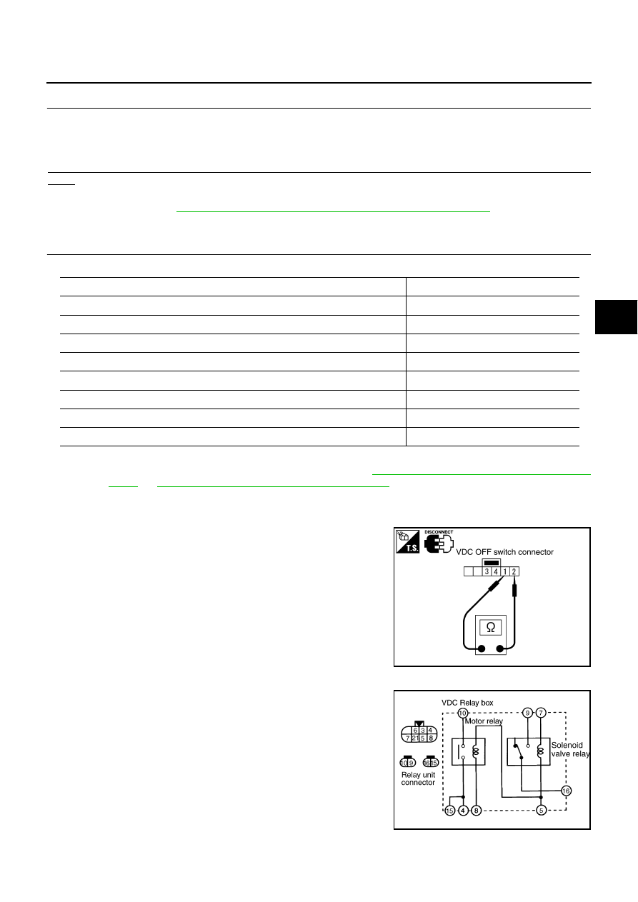
VDC OFF SWITCH
●
Disconnect VDC OFF switch connector. Check continuity
between terminal No. 1 and terminal No. 2.
VDC RELAY BOX
Disconnect VDC relay box connector. Check continuity, resistance
value, and insulation between any pair of terminals in VDC relay box.
Normal
Error (example)
Models with ICC system
Models without ICC system
CAN COMM: OK
CAN COMM: OK
CAN COMM: OK
CAN CIRC1: OK
CAN CIRC1: OK
CAN CIRC 1: UNKWN
CAN CIRC 2: OK
CAN CIRC 2: OK
CAN CIRC 2: UNKWN
CAN CIRC3: OK
CAN CIRC3: OK
CAN CIRC 3: UNKWN
CAN CIRC 4: OK
CAN CIRC 4: OK
CAN CIRC 4: UNKWN
CAN CIRC 5: OK
CAN CIRC 5: UNKWN
CAN CIRC 5: UNKWN
CAN CIRC 6: OK
CAN CIRC 6: OK
CAN CIRC 6: UNKWN
No. 1 to No. 2:
Pressing switch will establish continuity, releasing
it will break continuity.
SFIA0848E
SFIA0882E