Infiniti F50. Manual - part 271


  Index      Infiniti     Infiniti F50 - service repair manual 2006 year


Search            


Content   ..  269  270  271  272   ..


Infiniti F50. Manual - part 271


TROUBLE DIAGNOSIS

BRC-27

C

D

E

G

H

I

J

K

L

M

A

B

BRC

×

: Applicable

–: Not applicable

SELF-DIAGNOSIS
Description

If a malfunction is detected in system, ABS warning lamp, VDC OFF indicator lamp, and SLIP indicator lamp
on meter turn on. In this case, perform self-diagnosis as follows:

Operation Procedure

1.

Perform 

BRC-39, "Basic Inspection"

  using information from customer.
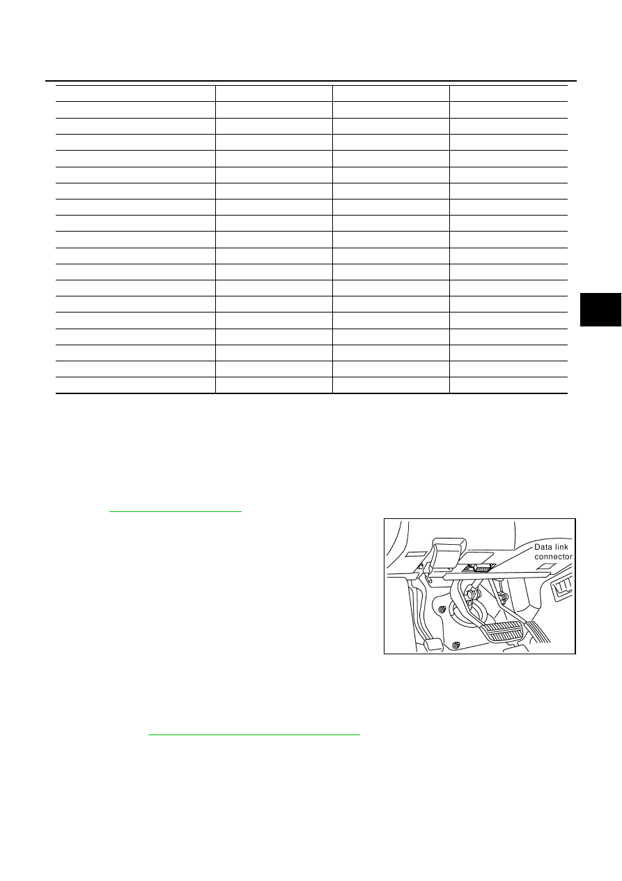
2.

After ignition switch is turned OFF, connect CONSULT-II and
CONSULT-II CONVERTER to data link connector (data link con-
nector is on lower instrument cover).

3.

Start engine and drive at approximately 30 km/h (19 MPH) for
approximately 1 minute.

4.

After stopping vehicle, with engine still idling, touch “START
(NISSAN BASED VHCL)”, “VDC”, and “SELF-DIAG RESULTS”
on CONSULT-II screen in this order.

CAUTION:

Just after starting engine, or turning ignition switch ON,
“VDC” may not be displayed on system selection screen
even if “START (NISSAN BASED VHCL)” is touched. In this
case, start self-diagnosis again from step 2. If it cannot be shown after several attempts, VDC/TCS/
ABS control unit may have malfunctioned. Repair or replace control unit.

5.

Self-diagnosis result is displayed. (If necessary, touch “PRINT” to print self-diagnosis result.)

When “NO FAILURE” is shown, check ABS warning lamp, VDC OFF indicator lamp, SLIP indicator
lamp. Refer to

BRC-37, "For Fast and Accurate Diagnosis"

 . 

CONSULT-II self-diagnosis results are displayed without regard to occurrence timing. In some cases
later ones (timing value is small) appear on next screen.

6.

Go to appropriate “Inspection” chart according to “Display Item List”, and repair or replace as necessary.

7.

Start engine and drive at approximately 30 km/h (19 MPH) for approximately 1 minute.

CAUTION:

Check again to make sure that there is no malfunction on other parts.

EV SIGNAL FL

×

×

×

AV SIGNAL FL

×

×

×

EV SIGNAL RR

×

×

×

AV SIGNAL RR

×

×

×

EV SIGNAL RL

×

×

×

AV SIGNAL RL

×

×

×

ABS ACTUATOR RELAY

×

ABS MOTOR RELAY

×

ABS WARNING LAMP

×

×

ABS CONT VOLT

×

×

VDC/TCS/ABS C/U

×

ABS MOTOR

×

×

CAN COMM

×

×

ENGINE SPEED SIGNAL

×

GEAR POSITION

×

OFF SW

×

VDC OFF LAMP

×

×

THRTL OPENING

×

Item

Self-diagnosis

Data monitor

Active test

PBIB0196E

BRC-28

TROUBLE DIAGNOSIS

8.

Turn ignition switch OFF to prepare for erasing memory.

9.

Start engine and touch “START (NISSAN BASED VHCL)”, “VDC”, “SELF-DIAGNOSIS RESULTS”, and
“ERASE MEMORY” on CONSULT-II screen in this order to erase memory.

CAUTION:

If memory cannot be erased, go to step 6.

10. Drive vehicle at approximately 30 km/h (19 MPH) and check that ABS warning lamp, VDC OFF indicator

lamp, and SLIP indicator lamp stay off.

Display Item List

Malfunction system

Malfunction detecting condition

Check system

FR LH SENSOR- 1

Circuit of front LH wheel sensor is open

Wheel sensor and circuit
 [Inspection 1] Note 1 

BRC-40

RR RH SENSOR- 1

Circuit of rear RH wheel sensor is open

FR RH SENSOR- 1

Circuit of front RH wheel sensor is open

RR LH SENSOR- 1

Circuit of rear LH wheel sensor is open

FR LH SENSOR- 2

Circuit of front LH wheel sensor is shorted, or sensor power volt-
age is unusual. Control unit cannot identify sensor pulses, 
because of large gap between wheel sensor and sensor rotor.

RR RH SENSOR- 2

Circuit of rear RH wheel sensor is shorted, or sensor power volt-
age is unusual. Control unit cannot identify sensor pulses, 
because of large gap between wheel sensor and sensor rotor.

FR RH SENSOR- 2

Circuit of front RH wheel sensor is shorted, or sensor power volt-
age is unusual. Control unit cannot identify sensor pulses, 
because of large gap between wheel sensor and sensor rotor.

RR LH SENSOR- 2

Circuit of rear LH wheel sensor is shorted, or sensor power volt-
age is unusual. Control unit cannot identify sensor pulses, 
because of large gap between wheel sensor and sensor rotor.

MAIN RELAY

During ABS actuator relay operation with OFF, when actuator 
relay turns ON or when control line for relay is shorted to ground.

Actuator relay and circuit
[Inspection 9] 

BRC-51


During ABS actuator relay operation with ON, when actuator 
relay turns OFF or when control line for relay is open.

STOP LAMP SW

Stop lamp switch circuit is open.

Stop lamp switch and cir-
cuit
[Inspection 10] 

BRC-53

PRESS SEN CIRCUIT

Pressure sensor signal line is open or shorted, or pressure sen-
sor is malfunctioning.

Pressure sensor and cir-
cuit [Inspection 4] 

BRC-

43

ST ANGLE SEN CIRCUIT

Neutral position of steering angle sensor is dislocated, or steer-
ing angle sensor is malfunctioning.

Steering angle sensor 
and circuit [Inspection 5] 

BRC-44

YAW RATE SENSOR

Yaw rate sensor has generated an error, or yaw rate sensor sig-
nal line is open or shorted.

Yaw rate/Side G-sensor 
and circuit
[Inspection 6] 

BRC-46

TROUBLE DIAGNOSIS

BRC-29

C

D

E

G

H

I

J

K

L

M

A

B

BRC

FR LH IN ABS SOL

Circuit of front LH IN ABS solenoid is open or shorted, or control 
line is open or shorted to power supply or ground.

Solenoid and circuit
[Inspection 7] 

BRC-47

FR LH OUT ABS SOL

Circuit of front LH OUT ABS solenoid is open or shorted, or con-
trol line is open or shorted to power supply or ground.

RR RH IN ABS SOL

Circuit of rear RH IN ABS solenoid is open or shorted, or control 
line is open or shorted to power supply or ground.

RR RH OUT ABS SOL

Circuit of rear RH OUT ABS solenoid is open or shorted, or con-
trol line is open or shorted to power supply or ground.

FR RH IN ABS SOL

Circuit of front RH IN ABS solenoid is open or shorted, or control 
line is open or shorted to power supply or ground.

FR RH OUT ABS SOL

Circuit of front RH OUT ABS solenoid is open or shorted, or con-
trol line is open or shorted to power supply or ground.

RR LH IN ABS SOL

Circuit of rear LH IN ABS solenoid is open or shorted, or control 
line is open or shorted to power supply or ground.

RR LH OUT ABS SOL

Circuit of rear LH OUT ABS solenoid is open or shorted, or con-
trol line is open or shorted to power supply or ground.

PRIMARY SIDE
USV CIRCUIT

Circuit of primary-side VDC switch-over valve 1 is open or 
shorted, or control line is open or shorted to power supply or 
ground.

VDC switch-over valve 
and circuit
[Inspection 7] 

BRC-47

SECONDARY SIDE USV CIR-
CUIT

Circuit of secondary-side VDC switch-over valve 1 is open or 
shorted, or control line is open or shorted to power supply or 
ground.

PRIMARY SIDE HSV CIRCUIT

Circuit of primary-side VDC switch-over valve 2 is open or 
shorted, or control line is open or shorted to power supply or 
ground.

SECONDARY SIDE HSV CIR-
CUIT

Circuit of secondary-side VDC switch-over valve 2 is open or 
shorted, or control line is open or shorted to power supply or 
ground.

PUMP MOTOR ACTUATOR RLY 

During actuator motor operation with ON, when actuator motor 
turns OFF or when control line for actuator motor relay is open.

Actuator motor, motor 
relay, and circuit
[Inspection 8] 

BRC-49

During actuator motor operation with OFF, when actuator motor 
turns ON or when control line for relay is shorted to ground.

LOW POWER VOLTAGE

VDC/TCS/ABS control unit power voltage is too low.

VDC/TCS/ABS control 
unit power supply and 
ground circuits
[Inspection 11] 

BRC-54

ST ANGLE SEN SIGNAL

Neutral position correction of steering angle sensor is not fin-
ished.

Neutral position adjust-
ment of steering angle 
sensor [Inspection 14] 

BRC-57

ST ANG SEN COM CIR

CAN communication line or steering angle sensor has generated 
an error.

Steering angle sensor 
and CAN communication 
line
[Inspection 16] 

BRC-58


SIDE G-SEN CIRCUIT

Side G-sensor is malfunctioning, or signal line of side G-sensor is 
open or shorted.

Yaw rate/Side G-sensor 
and circuit
[Inspection 6] 

BRC-46

EMERGENCY BRAKE

VDC/TCS/ABS control unit malfunction (pressure increase is too 
much or too little.)

VDC/TCS/ABS control 
unit
[Inspection 13] 

BRC-56

CONTROLLER FAILURE

Internal malfunction of VDC/TCS/ABS control unit

VDC/TCS/ABS control 
unit
[Inspection 3] 

BRC-42

Malfunction system

Malfunction detecting condition

Check system

BRC-30

TROUBLE DIAGNOSIS

Note 1. If wheel sensor 2 for each wheel is indicated, check control unit power supply voltage in addition to
wheel sensor circuit check.
Note 2. If multiple malfunctions are detected including CAN communication line [U1000], perform diagnosis for
CAN communication line first.

DATA MONITOR

For details of data monitor function, refer to “CONSULT-II Instruction Manual”.

Operation Procedure

1.

Turn ignition switch OFF.

2.

Connect CONSULT-II to and CONSULT-II CONVERTER data link connector.

3.

Turn ignition switch ON.

4.

Touch “START (NISSAN BASED VHCL)” on display.

5.

Touch “VDC” on display.

NOTE:
Just after starting engine, or turning ignition switch ON, “VDC” may not be displayed on system selection
screen even if “START (NISSAN BASED VHCL)” is touched. In this case, start self-diagnosis again from
step 2. 

6.

Touch “DATA MONITOR”.

7.

Return to monitor item selection screen, and touch any of “CONTROL UNIT INPUT ITEM”, “MAIN ITEM”
or “ITEM MENU SELECTION”. Refer to 

BRC-30, "Display Item List"

 .

8.

Touch “START”.

9.

Screen of data monitor is displayed.

Display Item List

SHIFT POSITION ERROR

P-position switch stuck to ON or TCM internal malfunction, VDC/
TCS/ABS control unit internal malfunction.

TCM and circuit
VDC/TCS/ABS control 
unit and circuit
[Inspection 12] 

BRC-56

CAN COMM CIRCUIT

CAN communication line is open or shorted.

VDC/TCS/ABS control unit internal malfunction

Battery voltage for EMC is suddenly interrupted for approxi-
mately 0.5 seconds or more.

Communication line 
between VDC/TCS/
ABS control unit and 
other control units
[Inspection 16] Note 2 

BRC-58

BR FLUID LEVEL LOW

Brake fluid level drops or communication line between VDC/
TCS/ABS control unit and brake fluid level sensor is open or 
shorted. 

Communication line 
between VDC/TCS/
ABS control unit and 
brake fluid sensor, and 
brake warning lamp

Reservoir tank fluid 
level
[Inspection 15

BRC-

57

ENGINE SIGNAL 2-6

Major engine component is malfunctioning.

Engine system
[Inspection 2] 

BRC-42

Malfunction system

Malfunction detecting condition

Check system

Item (Unit)

Monitor item selection

Remarks

ECU input 

signals

Main item

(Monitor item 

selection)

 selection 

from menu

CAN diagno-

sis support

Monitor

GEAR POSITION

×

×

×

Gear position judged by PNP 
switch signal is displayed.

VHCL SPEED FR

×

×

×

Wheel speed calculated by 
front RH wheel sensor signal 
is displayed.


Content   ..  269  270  271  272   ..