Infiniti F50. Manual - part 210
REMOTE KEYLESS ENTRY SYSTEM
BL-87
C
D
E
F
G
H
J
K
L
M
A
B
BL
CHECK REAR DOOR SWITCH
1.
CHECK REAR DOOR SWITCH INPUT SIGNAL
With CONSULT-II
Check rear door switch (“DOOR SW-RR” and “DOOR SW-RL”) in “DATA MONITOR” mode with CONSULT-II.
Without CONSULT-II
Check front door switch in “SWITCH MONITOR” mode.Refer to
.
OK or NG
OK
>> Rear door switch is OK.
NG
>> GO TO 2
2.
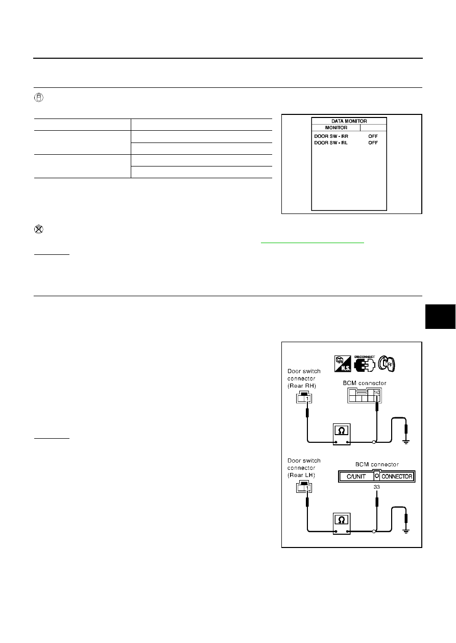
CHECK DOOR SWITCH
1.
Turn ignition switch OFF.
2.
Disconnect door switch and BCM connector.
3.
Check continuity between rear door switch connector D62 (rear LH), D82 (rear RH) terminal 1 (W) and
BCM connector M4 (rear LH), B4 (rear RH) terminal 33 (W), 143 (W/L).
4.
Check continuity between rear door switch connector D62 (rear
LH), D82 (rear RH) terminal 1(W) and ground.
OK or NG
OK
>> GO TO 3.
NG
>> Repair or replace harness.
Monitor item
Condition
DOOR SW-RR
OPEN
: ON
CLOSE
: OFF
DOOR SW-RL
OPEN
: ON
CLOSE
: OFF
PIIA3117E
Rear door switch LH
1 (W) – 33 (W)
: Continuity should exist.
Rear door switch RH
1 (W) – 143 (W/L)
: Continuity should exist.
1 (W) – Ground
: Continuity should not exist.
PIIA3119E