Infiniti F50. Manual - part 188


  Index      Infiniti     Infiniti F50 - service repair manual 2006 year


Search            


Content   ..  186  187  188  189   ..


Infiniti F50. Manual - part 188


NAVIGATION SYSTEM

AV-117

C

D

E

F

G

H

I

J

L

M

A

B

AV

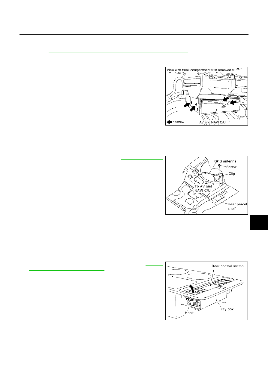
Removal and Installation of AV and NAVI Control Unit

EKS001MI

REMOVAL

1.

Refer to 

AV-53, "Precautions for AV and NAVI Control Unit Replacement"

 . Take a note of necessary

items.

2.

Remove trunk room trim. Refer to  

EI-52, "TRUNK ROOM TRIM & TRUNK LID FINISHER"

 .

3.

Remove screws and remove the AV and NAVI control unit.

INSTALLATION

Install in the reverse order of removal.

Removal and Installation of GPS Antenna

EKS001MJ

REMOVAL

1.

Remove rear parcel shelf finisher. Refer to 

EI-39, "REAR PAR-

CEL SHELF FINISHER"

 .

2.

Remove screws and remove the GPS antenna.

INSTALLATION

Install in the reverse order of removal.

Removal and Installation of Steering Wheel Switch

EKS001MK

Refer to 

SRS-39, "DRIVER AIR BAG MODULE"

 .

Removal and Installation of Rear Control Switch

EKS001ML

REMOVAL

1.

Remove the tray box from the center armrest. Refer to 

SE-202,

"CENTER SEATBACK ASSEMBLY"

 .

2.

Remove the rear control switch from the tray box.

INSTALLATION

Install in the reverse order of removal.

SKIA3581E

SKIA0388E

SKIA0390E

AV-118

NAVIGATION SYSTEM

Removal and Installation of Rear Control Cancel Switch

EKS006FZ

REMOVAL

1.

Remove front interior lamp. Refer to 

LT-107, "Removal and

Installation"

 .

2.

Remove rear control cancel switch from front interior lamp.

INSTALLATION

Install in the reverse order of removal.

SKIA3551E

BL-1

BODY, LOCK & SECURITY SYSTEM

I  BODY

CONTENTS

C

D

E

F

G

H

J

K

L

M

SECTION 

A

B

BL

BODY, LOCK & SECURITY SYSTEM

PRECAUTIONS .......................................................... 5

Precautions for Supplemental Restraint System 
(SRS) “AIR BAG” and “SEAT BELT PRE-TEN-
SIONER” .................................................................. 5
Precautions for work  ................................................ 5
Wiring Diagnosis and trouble Diagnosis  .................. 5

PREPARATION ........................................................... 6

Special Service Tool  ................................................. 6
Commercial Service Tool  ......................................... 6

SQUEAK AND RATTLE TROUBLE DIAGNOSES ..... 7

Work Flow  ................................................................ 7

CUSTOMER INTERVIEW ..................................... 7
DUPLICATE THE NOISE AND TEST DRIVE  ....... 8
CHECK RELATED SERVICE BULLETINS  ........... 8
LOCATE THE NOISE AND IDENTIFY THE 
ROOT CAUSE  ...................................................... 8
REPAIR THE CAUSE  ........................................... 8
CONFIRM THE REPAIR  ....................................... 9

Generic Squeak and Rattle Troubleshooting  ........... 9

INSTRUMENT PANEL  .......................................... 9
CENTER CONSOLE ............................................. 9
DOORS ................................................................. 9
TRUNK ................................................................ 10
SUNROOF/HEADLINER ..................................... 10
SEATS ................................................................. 10
UNDERHOOD ..................................................... 10

Diagnostic Worksheet  .............................................11

HOOD ....................................................................... 13

Fitting Adjustment  .................................................. 13

FRONT END HEIGHT ADJUSTMENT AND LAT-
ERAL/LONGITUDINAL CLEARANCE ADJUST-
MENT .................................................................. 13
SURFACE HEIGHT ADJUSTMENT  ................... 14

Removal and Installation of Hood Assembly .......... 15
Removal and Installation of Hood Lock Control  ..... 16

REMOVAL ........................................................... 16
INSTALLATION ................................................... 17

Hood Lock Control Inspection  ................................ 17

POWER DOOR LOCK SYSTEM  .............................. 19

Component Parts and Harness Connector Location 

... 19

System Description ................................................. 20

POWER SUPPLY AND GROUND  ...................... 20
OPERATION ........................................................ 20

Schematic ............................................................... 21
Wiring Diagram – D/LOCK –  .................................. 22
Terminals and Reference Value for BCM  ............... 29
Terminals and Reference Value for Driver Door Con-
trol Unit (LCU01) ..................................................... 30
Terminals and Reference Value for Passenger and 
Rear LH, RH Door Control Units  ............................ 30
Work Flow ............................................................... 31
Preliminary Check  .................................................. 31

POWER SUPPLY AND GROUND CIRCUIT 
INSPECTION ...................................................... 31

CONSULT-II Function ............................................. 33

DIAGNOSTIC ITEMS DESCRIPTION ................. 33
CONSULT-II BASIC OPERATION PROCEDURE 

... 34

IVMS COMMUNICATION INSPECTION ............. 35
SELF-DIAGNOSIS RESULTS  ............................. 37
DATA MONITOR  ................................................. 37
ACTIVE TEST  ..................................................... 37

On Board Diagnosis  ............................................... 38

DIAGNOSIS ITEM  ............................................... 38
COMMUNICATION DIAGNOSIS ......................... 38
COMMUNICATION SYSTEM A  .......................... 40
COMMUNICATION SYSTEM B  .......................... 40
COMMUNICATION SYSTEM C  .......................... 40
SWITCH MONITOR  ............................................ 41
POWER DOOR LOCK SYSTEM SELF-DIAG-
NOSIS ................................................................. 42

Symptom Chart ....................................................... 43
Check Communication Line .................................... 43
Check Door Lock and Unlock Switch  ..................... 44
Check Door Lock Actuator (Driver Side)  ................ 45
Check Door Lock Actuator (Passenger, Rear LH, 
RH) ......................................................................... 45
Check Front Door Key Cylinder Switch  .................. 46
Check Key Switch ................................................... 47

BL-2

Check Front Door Switch ........................................ 48
Check Door Unlock Sensor  .................................... 50

REMOTE KEYLESS ENTRY SYSTEM ..................... 52

Component Parts and Harness Connector Location ... 52
Component Parts and Harness Connector Location ... 53
System Description ................................................. 53

POWER SUPPLY AND GROUND ....................... 53
OPERATING PROCEDURE ................................ 54
POWER DOOR LOCK OPERATION ................... 54
HAZARD AND HORN REMINDER  ..................... 54
OPERATING FUNCTION OF HAZARD AND 
HORN REMINDER .............................................. 54
TRUNK LID OPENER OPERATION .................... 55
PANIC ALARM OPERATION ............................... 55
KEYLESS POWER WINDOW DOWN (OPEN) 
OPERATION ........................................................ 55
AUTO DOOR LOCK OPERATION  ...................... 55
INTERIOR LAMP AND STEP LAMP OPERA-
TION .................................................................... 55

Schematic ............................................................... 56
Wiring Diagram – KEYLES –  .................................. 57
Terminal and Reference Value for BCM  ................. 67
Terminal and Reference Value for Driver Door Con-
trol Unit (LCU01) ..................................................... 68
Terminal and Reference Value for Passenger And 
Rear LH, RH Door Control Unit  .............................. 68
Work Flow ............................................................... 69
Preliminary Check  .................................................. 70

POWER SUPPLY AND GROUND CIRCUIT 
INSPECTION ....................................................... 70
SYSTEM INSPECTION  ....................................... 71

CONSULT–II Function  ............................................ 72

DIAGNOSTIC ITEMS DESCRIPTION ................. 72
CONSULT-II BASIC OPERATION PROCEDURE 

... 73

IVMS COMMUNICATION INSPECTION  ............. 73
DATA MONITOR .................................................. 75
ACTIVE TEST  ..................................................... 76
WORK SUPPORT  ............................................... 76

On Board Diagnosis  ............................................... 77

DIAGNOSIS ITEM  ............................................... 77
COMMUNICATION DIAGNOSIS ......................... 77
COMMUNICATION SYSTEM A ........................... 79
COMMUNICATION SYSTEM B ........................... 79
COMMUNICATION SYSTEM C  .......................... 79
SWITCH MONITOR  ............................................ 80

Trouble Diagnosis Chart by Symptom  .................... 80
Check Electronic Key  ............................................. 82
Check ACC Power .................................................. 83
Check Key Switch ................................................... 84
Check Door Switch  ................................................. 85

CHECK FRONT DOOR SWITCH ........................ 85
CHECK REAR DOOR SWITCH  .......................... 87

Check Trunk Lid Opener Cancel Switch  ................. 88
Check Trunk Lid Opener Actuator  .......................... 89
Check Trunk Open Signal ....................................... 90
Check Horn Circuit  ................................................. 91
Check Hazard Reminder Operation  ....................... 93
Check Remote Keyless Entry Receiver .................. 94

Check Door Lock and Unlock Switch ......................96
Check Hazard Function  ..........................................96
Check Horn Function  ..............................................96
Check Headlamp Function ......................................96
Check Map Lamp Function  .....................................97
Electronic Key Battery Replacement  ......................97

CHECK ELECTRONIC KEY BATTERY ...............98

ID Code Entry Procedure ........................................99

PROCEDURE 1 (WITHOUT CONSULT-II) ..........99
PROCEDURE 2 (WITH CONSULT-II)  ...............100

Removal and Installation of Remote Keyless Entry 
Receiver ................................................................101

REMOVE ...........................................................101
INSTALLATION ..................................................101

DOOR ......................................................................102

Fitting Adjustment  .................................................102

FRONT DOOR ...................................................102
REAR DOOR  .....................................................102
STRIKER ADJUSTMENT  ..................................102

Removal and Installation of Front Door  ................103

REMOVAL ..........................................................103
INSTALLATION ..................................................104

Removal and Installation of Rear Door  .................104

REMOVAL ..........................................................104
INSTALLATION ..................................................104

Door Weatherstrip  .................................................105

FRONT DOOR LOCK ..............................................106

Component Structure  ............................................106
Inspection and Adjustment ....................................106

EXTERIOR HANDLE ROD ADJUSTMENT .......106

Removal and Installation .......................................106

REMOVAL ..........................................................106
INSTALLATION ..................................................107

Disassembly and Assembly  ..................................108

DISASSEMBLY ..................................................108
ASSEMBLY ........................................................108

REAR DOOR LOCK  ................................................109

Components ..........................................................109
Inspection and Adjustment ....................................109

EXTERIOR HANDLE ROD ADJUSTMENT .......109

Removal and Installation of Door Lock  .................109

REMOVAL ..........................................................109
INSTALLATION .................................................. 110

Disassembly and Assembly  .................................. 110

DISASSEMBLY .................................................. 110
ASSEMBLY ........................................................ 111

TRUNK LID .............................................................. 112

Fitting Adjustment  ................................................. 112

LONGITUDINAL AND LATERAL CLEARANCE 
ADJUSTMENT ................................................... 112
SURFACE HEIGHT ADJUSTMENT  .................. 112

Removal and Installation of Trunk Lid Assembly  .. 113

REMOVAL .......................................................... 113
INSTALLATION .................................................. 113

Removal and Installation of Trunk Lid Stay ........... 113

REMOVAL .......................................................... 113
INSTALLATION .................................................. 114

Removal and Installation of Trunk Lid Lock  .......... 114

REMOVAL .......................................................... 114


Content   ..  186  187  188  189   ..