Infiniti F50. Manual - part 182


  Index      Infiniti     Infiniti F50 - service repair manual 2006 year


Search            


Content   ..  180  181  182  183   ..


Infiniti F50. Manual - part 182


NAVIGATION SYSTEM

AV-93

C

D

E

F

G

H

I

J

L

M

A

B

AV

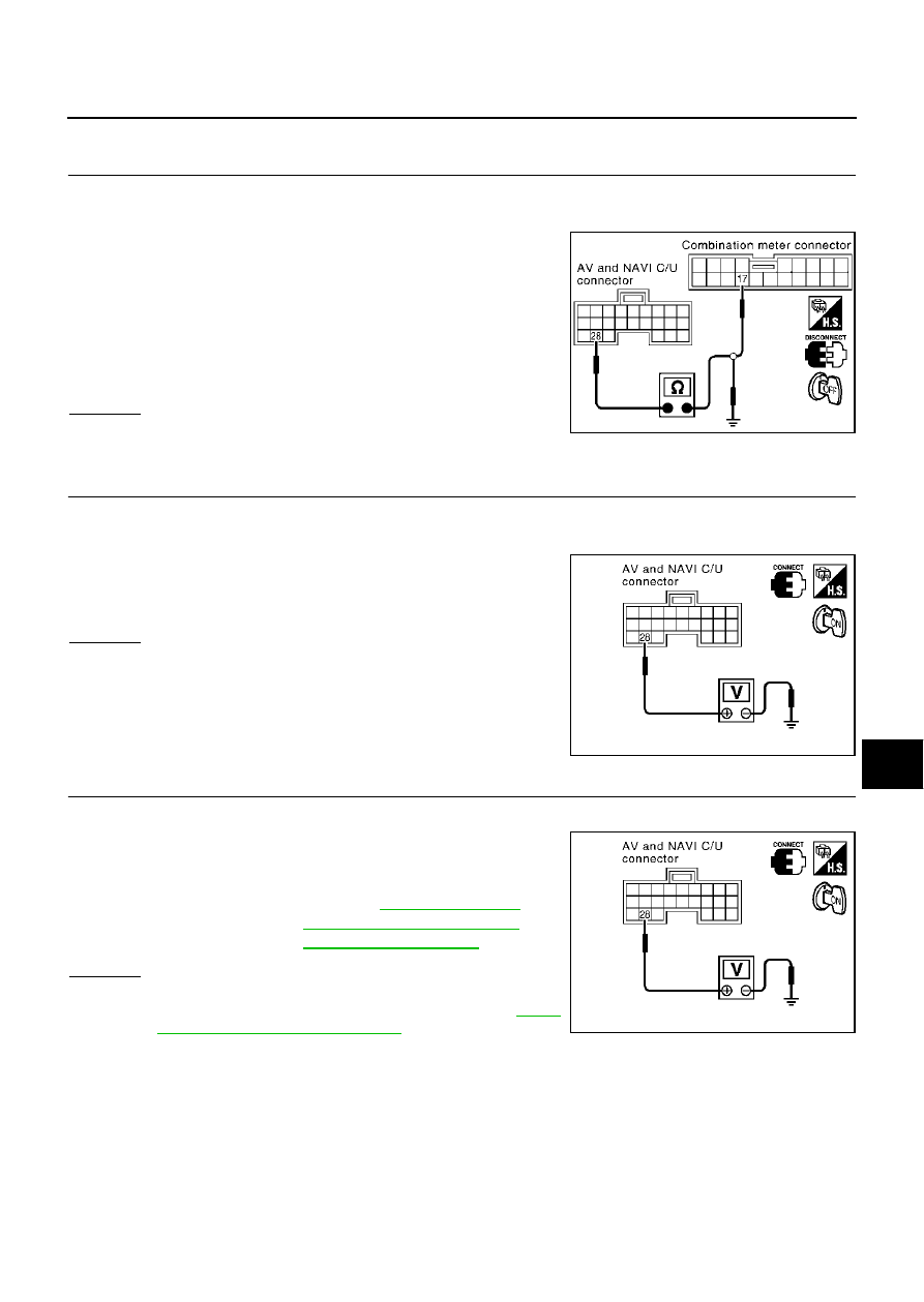
Vehicle Speed Signal Check

EKS001LZ

1. 

HARNESS CHECK

1.

Turn ignition switch OFF.

2.

Disconnect AV and NAVI control unit connector and combination meter connector.

3.

Check continuity between AV and NAVI control unit harness
connector B29 terminal 28 (OR/L) and combination meter har-
ness connector M41 terminal 17 (OR/L).

4.

Check continuity between AV and NAVI control unit harness
connector B29 terminal 28 (OR/L) and ground.

OK or NG

OK

>> GO TO 2.

NG

>> Repair harness.

2. 

VEHICLE SPEED SIGNAL CHECK 1

1.

Connect AV and NAVI control unit connector and combination meter connector.

2.

Turn ignition switch ON.

3.

Check voltage between AV and NAVI control unit harness con-
nector B29 terminal 28 (OR/L) and ground.

OK or NG

OK

>> GO TO 3.

NG

>> Replace AV and NAVI control unit

3. 

VEHICLE SPEED SIGNAL CHECK 2

1.

Drive vehicle at a constant speed.

2.

Check the signal between AV and NAVI control unit harness
connector B29 terminal 28 (OR/L) and ground with CONSULT

ll

or oscilloscope.

OK or NG

OK

>> Replace AV and NAVI control unit.

NG

>> Check combination meter system, refer to 

DI-23,

"Inspection/Vehicle Speed Signal"

Continuity should exist.

Continuity should not exist.

SKIA3516E

Approx. 3.5V or more

SKIA3517E

28 (OR/L) - Ground

: Refer to 

AV-73, "Terminals 

and Reference Value for AV 
and NAVI Control unit"

 .

SKIA3517E

AV-94

NAVIGATION SYSTEM

Illumination Control Signal Check

EKS001M1

1. 

ILLUMINATION CONTROL SIGNAL CHECK

1.

Turn ignition switch ON.

2.

Check voltage between AV and NAVI control unit and ground.

OK or NG

OK

>> Replace AV and NAVI control unit.

NG

>> Check harness for open or short between AV and NAVI

control unit and BCM.

Ignition Signal Check

EKS001M2

1. 

IGNITION SIGNAL CHECK

1.

Disconnect the AV and NAVI control unit connector.

2.

Turn ignition switch ON.

3.

Check voltage between AV and NAVI control unit harness con-
nector B29 terminal 26 (W/G) and ground.

OK or NG

OK

>> Replace AV and NAVI control unit.

NG

>> Check harness for open or short between AV and NAVI

control unit and fuse.

Terminals

Lighting switch position

(+)

(–)

Connector

Terminal (Wire color)

1st or 2nd 

position

OFF

B29

25 (R/L)

Ground

Approx. 3.5V 

or more

Approx. 1.5V 

or less

SKIA3557E

Battery voltage should exist.

SKIA3518E

NAVIGATION SYSTEM

AV-95

C

D

E

F

G

H

I

J

L

M

A

B

AV

Reverse Signal Check

EKS001M3

1. 

REVERSE LAMP CHECK

1.

Turn ignition switch ON.

2.

A/T shift selector lever into R-position. Does “R” in the shift position indicator come on?

YES or NO

YES

>> GO TO 2.

NO

>> Check back-up lump system. Refer to 

LT-71, "BACK-UP LAMP"

 .

2. 

REVERSE SIGNAL CHECK

With the selector lever in R-position, Check voltage between AV and
NAVI control unit and ground.

OK or NG

OK

>> Replace AV and NAVI control unit.

NG

>> Check harness for open or short between AV and NAVI control unit and back-up lump position

relay.

Terminals

A/T selector lever position

(+)

(–)

Connector

Terminal 

(Wire color)

R-position

other than R-

position

B29

27(R/B)

Ground

Battery voltage

Approx. 3.0V or 

less

SKIA3558E

AV-96

NAVIGATION SYSTEM

RGB Screen Is Not Shown

EKS001M4

1. 

HARNESS CHECK

1.

Turn ignition switch OFF.

2.

Disconnect AV and NAVI control unit connector and Display connector.

3.

Check continuity between AV and NAVI control unit harness connector B30 terminal 12 (B) and Display
harness connector M82 terminal 8 (LG).

4.

Check continuity between AV and NAVI control unit harness
connector B30 terminal 13 (W) and Display harness connector
M82 terminal 5 (L/Y).

5.

Check continuity between NAVI control unit harness connector
B30 terminal 12 (B), 13 (W) and ground.

OK or NG

OK

>> GO TO 2.

NG

>> Repair harness.

2. 

HORIZONTAL SYNCHRONIZATION SIGNAL CHECK

1.

Connect AV and NAVI control unit connector and Display connector.

2.

Turn ignition switch ON.

3.

Check the signal between AV and NAVI control unit harness
connector B30 terminals 13 (W) and 14 with CONSULT-ll or
oscilloscope.

OK or NG

OK

>> GO TO 3.

NG

>> Replace Display.

3. 

RGB AREA SIGNAL CHECK

1.

Press “INFO” switch.

2.

Check the signal between AV and NAVI control unit harness
connector B30 terminals 12 (B) and 14 with CONSULT-ll or
oscilloscope.

OK or NG

OK

>> Replace Display.

NG

>> Replace AV and NAVI control unit.

Continuity should exist.

Continuity should exist.

Continuity should not exist.

SKIA3559E

13 (W) - 14

: Refer to 

AV-73, "Terminals and Refer-

ence Value for AV and NAVI Control unit"


.

SKIA3519E

12 (B) -14

: Refer to 

AV-73, "Terminals and Refer-

ence Value for AV and NAVI Control unit"


.

SKIA3520E


Content   ..  180  181  182  183   ..