Infiniti F50. Manual - part 157


  Index      Infiniti     Infiniti F50 - service repair manual 2006 year


Search            


Content   ..  155  156  157  158   ..


Infiniti F50. Manual - part 157


REFRIGERANT LINES

ATC-153

C

D

E

F

G

H

I

K

L

M

A

B

ATC

REMOVAL

1.

Use a refrigerant collecting equipment (for HFC-134a) to dis-
charge the refrigerant.

2.

Remove front grille. Refer to 

EI-19, "FRONT GRILLE"

 .

3.

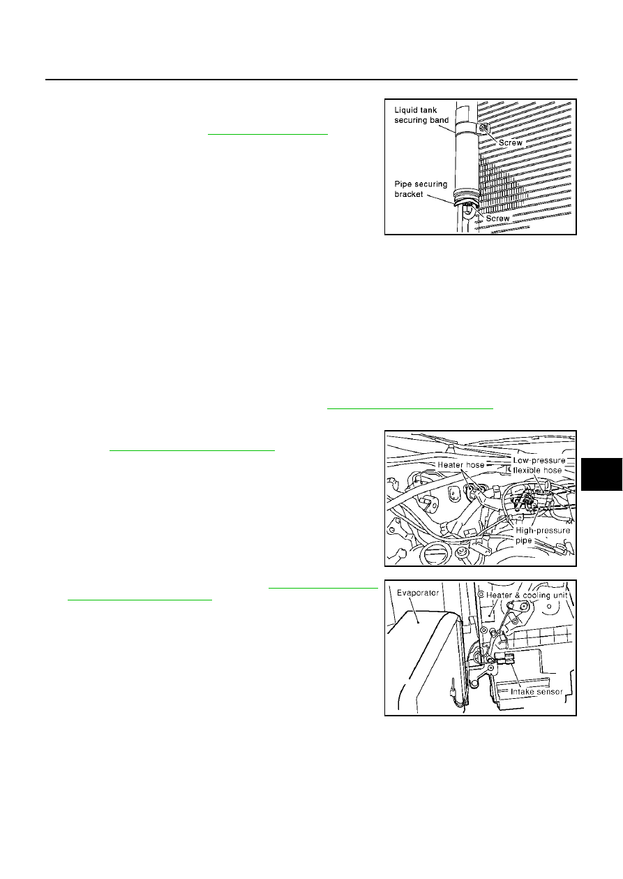
Unscrew, and remove the securing bracket piping.

4.

Unscrew liquid tank securing bands.

5.

Pull out the liquid tank and liquid tank securing bands through
the top.

INSTALLATION

Installation is basically the reverse order of removal.

CAUTION:

Replace refrigerant pressure sensor O-ring with a new one. Apply compressor oil prior to installation.

Evaporator

EJS000AD

REMOVAL

1.

Remove engine cover and air cleaner cover. Refer to 

EM-11, "ENGINE ROOM COVER"

 .

2.

Use a refrigerant collecting equipment (for HFC-134a) to discharge the refrigerant.

3.

Drain coolant from cooling system and disconnect heater hoses.
Refer to 

CO-9, "Changing Engine Coolant"

 .

4.

Disconnect low-pressure flexible hose and high-pressure pipe
from the evaporator.

CAUTION:

Cap or wrap the open ends of low-pressure flexible hose
and high-pressure pipe with a suitable material such as a
vinyl tape to avoid the entry of air.

5.

Remove heater & cooling unit. Refer to 

ATC-133, "HEATER  &

COOLING UNIT ASSEMBLY"

 .

6.

Remove cooler grommet, expansion valve cover, expansion
valve.

7.

Remove air mix door motor and mode door motor bracket.

8.

Remove evaporator cover.

9.

Slide the evaporator, then remove it from the heater & cooling
unit.

10. Remove intake sensor from the evaporator, then remove evapo-

rator.

SJIA0133E

Securing bracket piping mounting screws

Tightening torque

: 4.0 - 5.0 N·m (0.41 - 0.51 kg·m, 36 - 44 in-lb)

Liquid tank securing band mounting screw

Tightening torque

: 2.94 - 3.82 N·m (0.3 - 0.38 kg·m, 26 - 33 in-lb)

RJIA0318E

RJIA0110E

ATC-154

REFRIGERANT LINES

INSTALLATION

Installation is basically the reverse order of removal.

CAUTION:

Replace low-pressure flexible hose and high-pressure pipe O-rings with new ones. Apply com-
pressor oil prior to installation.

Mark mounting position of the intake sensor bracket.

Expansion Valve

EJS001YO

REMOVAL

1.

Remove engine cover and air cleaner cover. Refer to 

EM-11, "ENGINE ROOM COVER"

 .

2.

Use a refrigerant collecting equipment (for HFC-134a) to discharge the refrigerant.

3.

Drain coolant from cooling system and disconnect heater hoses.
Refer to 

CO-9, "Changing Engine Coolant"

 .

4.

Disconnect low-pressure flexible hose and high-pressure pipe
from the evaporator.

5.

Remove expansion valve cover.

6.

Remove expansion valve.

INSTALLATION

Installation is basically the reverse order of removal.

CAUTION:

Replace O-rings with new ones, then apply compressor oil to them when installing them.

When recharging refrigerant, check for leaks.

Bolt mounting the low-pressure flexible hose and high-pressure pipe

Tightening torque

: 2.9 - 5.9 N·m (0.29 - 0.6 kg·m, 26 - 52 in-lb)

RJIA0318E

RJIA0334E

Bolts mounting the expansion valve

Tightening torque

: 2.9 - 4.9 N·m (0.29 - 0.50 kg·m, 26 - 43 in-lb)

Bolt mounting the low-pressure flexible hose and high-pressure 
pipe

Tightening torque

: 2.9 - 5.9 N·m (0.29 - 0.6 kg·m, 26 - 52 in-lb)

REFRIGERANT LINES

ATC-155

C

D

E

F

G

H

I

K

L

M

A

B

ATC

Checking for Refrigerant Leaks

EJS000KI

Perform a visual inspection of all refrigeration parts, fittings, hoses and components for signs of A/C lubricant
leakage, damage and corrosion. A/C lubricant leakage may indicate an area of refrigerant leakage. Allow
extra inspection time in these areas when using either an electronic refrigerant leak detector or fluorescent
dye leak detector.
If dye is observed, confirm the leak with an electronic refrigerant leak detector. It is possible a prior leak was
repaired and not properly cleaned.
When searching for leaks, do not stop when one leak is found but continue to check for additional leaks at all
system components and connections.
When searching for refrigerant leaks using an electronic leak detector, move the probe along the suspected
leak area at 1 to 2 inches per second and no further than 1/4 inch from the component.

CAUTION:

Moving the electronic leak detector probe slower and closer to the suspected leak area will improve
the chances of finding a leak.

Checking System for Leaks Using the Fluorescent Leak Detector

EJS000KJ

1.

Check A/C system for leaks using the UV lamp and safety glasses (J-42220) in a low sunlight area (area
without windows preferable). Illuminate all components, fittings and lines. The dye will appear as a bright
green/yellow area at the point of leakage. Fluorescent dye observed at the evaporator drain opening indi-
cates an evaporator core assembly (tubes, core or expansion valve) leak.

2.

If the suspected area is difficult to see, use an adjustable mirror or wipe the area with a clean shop rag or
cloth.

3.

After the leak is repaired, remove any residual dye using dye cleaner (J-43872) to prevent future misdiag-
nosis.

4.

Perform a system performance check and verify the leak repair with an approved electronic refrigerant
leak detector.

NOTE:
Other gases in the work area or substances on the A/C components, for example, anti-freeze, windshield
washer fluid, solvents and lubricants, may falsely trigger the leak detector. Make sure the surfaces to be
checked are clean.
Clean with a dry cloth or blow off with shop air.
Do not allow the sensor tip of the detector to come in contact with any substance. This can also cause false
readings and may damage the detector.

Dye Injection

EJS000KK

(This procedure is only necessary when recharging the system or when the compressor has seized and was
replaced.)
1.

Check A/C system static (at rest) pressure. Pressure must be at least 345 kPa (50 psi).

2.

Pour one bottle (1/4 ounce / 7.4 cc) of the A/C refrigerant dye into the injector tool (J-41459).

3.

Connect the injector tool to the A/C LOW PRESSURE side service fitting.

4.

Start engine and switch A/C ON.

5.

When the A/C operating (compressor running), inject one bottle (1/4 ounce / 7.4 cc) of fluorescent dye
through the low-pressure service valve using dye injector tool J-41459 (refer to the manufacture's operat-
ing instructions).

6.

With the engine still running, disconnect the injector tool from the service fitting.

CAUTION:

Be careful when servicing the A/C system or replacing a component, pour the dye directly into the
open system connection and proceed with the service procedures.

7.

Operate the A/C system for a minimum of 20 minutes to mix the dye with the system oil. Depending on the
leak size, operating conditions and location of the leak, it may take anywhere from minutes to days for the
dye to penetrate a leak and become visible.

ATC-156

REFRIGERANT LINES

Electronic Refrigerant Leak Detector

EJS000KL

PRECAUTIONS FOR HANDLING LEAK DETECTOR

When performing a refrigerant leak check, use a J-41995 A/C leak
detector or equivalent. Ensure that the instrument is calibrated and
set properly as per the operating instructions.
The leak detector is a delicate device. In order to use the leak detec-
tor properly, read the operating instructions and perform any speci-
fied maintenance.

1.

Position probe approximately 5 mm (3/16 in) away from point to
be checked.

2.

When testing, completely circle each fitting with probe.

3.

Move probe along component approximately 25 to 50 mm (1 to
2 in)/sec.

SHA196FA

SHA707EA

SHA706E

SHA708EA


Content   ..  155  156  157  158   ..